Problem:
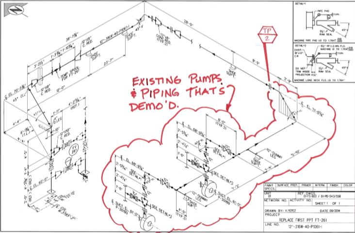
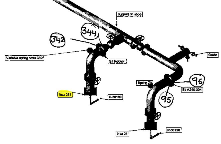
A chemical plant approached PT&P about the need for an expansion joint which was required as part of a replacement of Pumps and the addition of new pump discharge piping. As we started discussing the requirements, the client became concerned about whether the stress analysis they had conducted had properly specified the correct layout and expansion joint. The client used an expansion joint in their analysis on the vertical piping coming out of the pump nozzle.
The client requested a quote from PT&P to perform a stress analysis to determine the proper specification of the expansion joint and overall line. The client was highly restricted in space availability. PT&P provided a quote of <$10K for the stress analysis and expansion joint specification to be completed by:
- Pipe Stress Engineer with 30+ years of experience and former Secretary of Texas Society of Professional Engineers
- Expansion Joint Engineering Lead with over 30 years of experience

Input Data:
Operating Temp – 245oF; Operating Pressure – 150 psi; Steam Out Temp – 285oF; 12” SS A312 TP304 Pipe; 2” Insulation thickness; Specific gravity – 0.944; API 610 allowable nozzle loads
Challenges:
CAESAR treatment of expansion joints is much more simplistic than pipe supports. Various spring rates are input for the expansion joint along with information about tie rods. This allows CAESAR to utilize the spring rates to calculate thermal growth movements that will be absorbed by the lower spring rate of the expansion joint vs other components of the piping system. It does NOT calculate whether forces from thermal growth will cause excess stress on the expansion joint. For example, expansion joints are not designed to absorb significant torsional force. Proper design of Piping Systems with expansion joints requires both System expertise in Pipe Stress Engineering as well as component level expertise in Expansion Joints. PT&P is uniquely positioned to help customers as we have been doing Pipe Stress Engineering and Expansion Joint design and manufacturing for over 40 years.
Solution:
PT&P reviewed the CAESAR model from the client and determined that there was excess torsional force on the expansion joint in the customer design. In addition, the placement of the expansion joint on the vertical line would require an in-line pressure balanced expansion joint which is more expensive and requires maintenance of 3 bellows. NOTE: If an in-line pressure balanced expansion joint was not used, the force of pressure thrust would be placed on the pump which would cause excess force at the system operating pressure of 150 PSI.
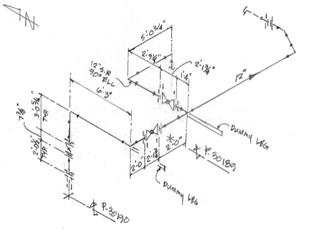
PT&P tried reducing the loads at the piping by eliminating the expansion joints, however, the loads were very high without the expansion joints. PT&P tried using the expansion joints in the horizontal piping coming out of the pumps, but the available spacing was not sufficient to fit in an expansion joint on one of the lines. PT&P worked with the client to change the elbow on the line from a long radius to a short radius thus providing sufficient space for the expansion joint in the horizontal piping.
With deep Expansion Joint expertise, PT&P was able to provide the client with exact space requirements with a spaced optimized design. In this case, PT&P designed a 2 PLY Inconel 625LCF expansion joint with a bellows convolution layout which minimized the length of the expansion joint.
On performing the stress analysis using the expansion joint, the stress code passed for the piping and the loads were within the allowable ranges, however, there was a high moment about one axis (Mz) causing a concern.

Fig: CAESAR output indicating high moment Mz along one axis on one pump
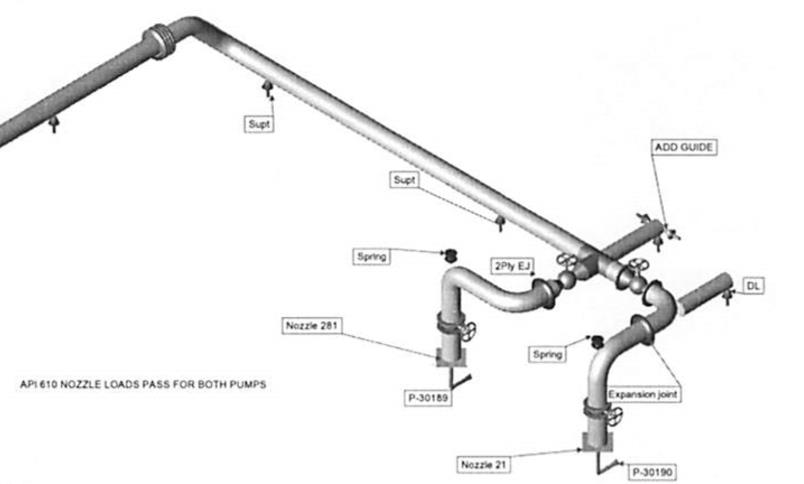
PT&P worked with the client to modify the piping by:
- Adding a loop at the horizontal piping
- Adding an Expansion Joint on the pump discharge horizontal piping
- Adding a spring support at the top of the pump discharge vertical piping
With these changes, the design passed the stress codes in the pump discharge piping and kept the loads at the nozzle within the allowable range.


Fig: CAESAR output indicating loads and moment within allowable range
Summary:
PT&P offers an exceptional value for a class of problems that are often not well served – small capital projects. In this case, the customer’s budget did not allow for the funding typically required to engage consulting experts with deep Pipe Stress and Expansion Joint design and engineering expertise. If the customer had proceeded with the original design, they would have likely suffered from ongoing maintenance issues on Expansion Joint and Pump.
PT&P is able to effectively serve small capital projects because it does not carry the overhead of a traditional professional services firm. We have 70+ design engineers on staff and a sales organization for our manufacturing business. This allows us to engage on small projects without having to keep dedicated consulting staff and trying to manage utilization rates for this staff.
While PT&P does not have the range of expertise of a typical engineering firm, we have extraordinarily deep expertise in Piping. This allows us to put world-class experts on small projects. In this case, it allowed us to place a Pipe Stress Engineer and Expansion Joint Engineer who each had over 30 years of experience on a very small project that cost the customer <$10K. This experience was highly valuable on this project as CAESAR does not “guide” a Pipe Stress Engineer into a proper overall system design incorporating expansion joints.
