Clevis Hangers
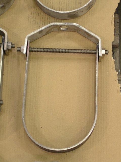
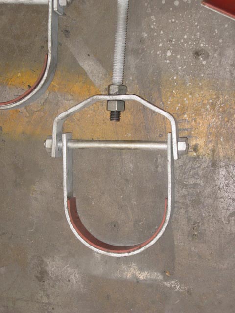
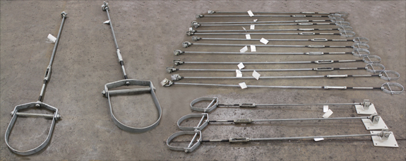
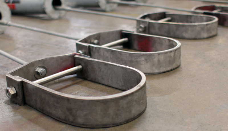
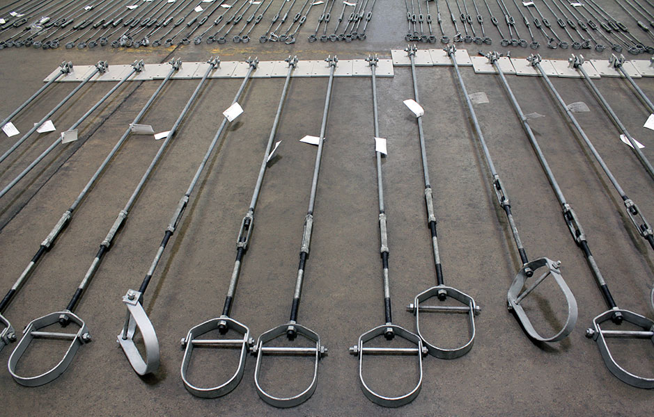
A clevis hanger is a pipe attachment providing vertical adjustment, consisting of a clevis type top bolted to a formed steel bottom strap. They are recommended for the suspension of non-insulated, stationary pipe lines.
Ammonia Plant
Chemical Plant
Clean Fuels
Commercial
Electric Plant
Energy Facility
Ethylene Plant
LLDPE Chemical Plant
LNG Plant
MTBE Plant
Natural Gas Combined Cycle Facility
Natural Gas Processing & Separation
Oil Refinery
Oil Sand Mine
Paper Manufacturer
See All
A trapeze hanger is a support assembly consisting of parallel vertical rods which are suspended from a structure and connected ...Continue Reading
More FAQs…
GENERAL DIMENSIONS & SPECIFICATIONS
- Fig. 83: Adjustable Clevis Hanger
- Fig. 89: Clevis Hanger for Insulated Lines
- Fig. 195: Roller Hanger
- Fig. 200: Trapeze Roller Hanger
Fig. 83: Adjustable Clevis Hanger
SIZE RANGE: 1/2 inches thru 30 inches
MATERIAL: Carbon steel
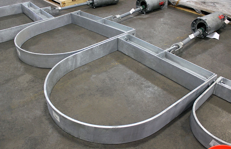
FINISH: Black or galvanized: furnished galvanized unless otherwise specified.
SERVICE: Recommended for the suspension of non-insulated, stationary pipe lines.
MAX. TEMP: 650°F.
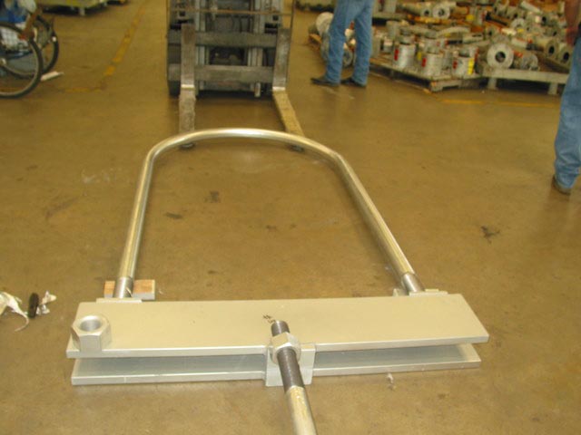
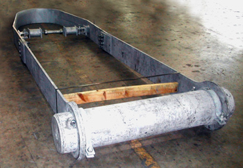
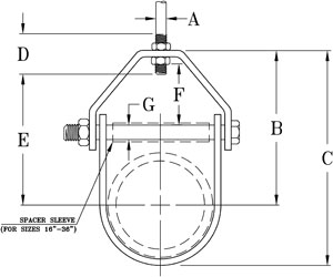
FEATURES: Designed with the yoke on outside of lower U-Strap so the yoke cannot slide toward the center of the bolt, thus bending of the bolt is minimized. Spacer sleeve used for size 16” thru 36”.
COMPONENTS: Top yoke, bottom strap, and bolt or stud with nut-assembled.
INSTALLATION: Hanger load nut ABOVE clevis must be tightened securely to assure proper hanger performance.
ORDERING: Specify figure number, pipe size, description and finish.
NOTE: Punched forming holes may be present on certain sizes of this clevis hanger. These holes are solely for the purpose of manufacturing and do not affect the structural integrity or load carrying capacities of these hangers.
PIPE SIZE | MAX. RECOM. LOAD, lbs. | WEIGHT (APPROX.) lbs. per 100 | SIZE OF STEEL | A | B | C | D | E | ADJUSTMENT | G | |
Upper | Lower | F | |||||||||
1/2 | 730 | 34 | 1/8 x 1 | 1/8 x 1 | 3/8 | 1 11/16 | 2 1/8 | 2 1/2 | 7/8 | 7/16 | 1/4 |
3/4 | 730 | 39 | 1/8 x 1 | 1/8 x 1 | 3/8 | 1 7/8 | 2 7/16 | 2 1/2 | 1 | 1/2 | 1/4 |
1 | 730 | 44 | 1/8 x 1 | 1/8 x 1 | 3/8 | 2 1/8 | 2 13/16 | 2 1/2 | 1 1/4 | 5/8 | 1/4 |
1 1/4 | 730 | 45 | 1/8 x 1 | 1/8 x 1 | 3/8 | 2 9/16 | 3 7/16 | 2 1/2 | 1 3/4 | 7/8 | 1/4 |
1 1/2 | 730 | 55 | 1/8 x 1 | 1/8 x 1 | 3/8 | 3 | 4 | 2 1/2 | 2 1/8 | 1 1/16 | 1/4 |
2 | 730 | 61 | 1/8 x 1 | 1/8 x 1 | 3/8 | 3 11/16 | 4 7/8 | 2 1/2 | 2 15/16 | 1 5/8 | 1/4 |
2 1/2 | 1350 | 140 | 3/16 x 1 1/4 | 3/16 x 1 1/4 | 1/2 | 4 11/16 | 6 1/8 | 3 | 3 13/16 | 2 | 3/8 |
3 | 1350 | 152 | 3/16 x 1 1/4 | 3/16 x 1 1/4 | 1/2 | 4 3/4 | 6 9/16 | 3 | 3 7/8 | 1 3/4 | 3/8 |
3 1/2 | 1350 | 170 | 3/16 x 1 1/4 | 3/16 x 1 1/4 | 1/2 | 4 15/16 | 6 15/16 | 3 | 4 1/16 | 1 3/4 | 3/8 |
4 | 1430 | 213 | 1/4 x 1 1/4 | 3/16 x 1 1/4 | 5/8 | 5 9/16 | 7 13/16 | 3 1/2 | 4 1/2 | 1 15/16 | 3/8 |
5 | 1430 | 244 | 1/4 x 1 1/4 | 3/16 x 1 1/4 | 5/8 | 6 3/16 | 9 | 3 1/2 | 5 1/8 | 1 3/4 | 1/2 |
6 | 1940 | 357 | 1/4 x 1 1/2 | 3/16 x 1 1/2 | 3/4 | 6 15/16 | 10 1/8 | 4 | 5 5/8 | 1 7/8 | 1/2 |
8 | 2000 | 497 | 1/4 x 1 3/4 | 3/16 x 1 3/4 | 7/8 | 8 3/8 | 12 5/8 | 4 1/4 | 7 | 2 1/8 | 5/8 |
10 | 3600 | 880 | 3/8 x 1 3/4 | 1/4 x 1 3/4 | 7/8 | 9 7/8 | 15 1/4 | 4 1/2 | 8 3/8 | 2 1/4 | 3/4 |
12 | 3800 | 1142 | 3/8 x 2 | 1/4 x 2 | 7/8 | 11 1/2 | 18 | 4 1/2 | 10 3/16 | 3 | 3/4 |
14 | 4200 | 1484 | 1/2 x 2 | 1/4 x 2 | 1 | 12 7/16 | 19 7/16 | 5 1/4 | 10 13/16 | 2 15/16 | 7/8 |
16 | 4600 | 2104 | 1/2 x 2 1/2 | 1/4 x 2 1/2 | 1 | 14 1/16 | 22 1/16 | 6 | 12 7/16 | 2 5/8 | 1 |
18 | 4800 | 2442 | 1/2 x 2 1/2 | 1/4 x 2 1/2 | 1 | 15 1/2 | 24 3/4 | 6 1/2 | 13 15/16 | 3 7/8 | 1 1/8 |
20 | 4800 | 4265 | 3/4 x 3 | 3/8 x 3 | 1 1/4 | 17 1/4 | 27 3/8 | 7 | 14 7/16 | 4 | 1 1/4 |
24 | 4800 | 4853 | 3/4 x 3 | 3/8 x 3 | 1 1/4 | 19 5/8 | 31 5/8 | 7 1/2 | 17 1/2 | 4 1/4 | 1 1/4 |
30 | 6000 | 6964 | 1 x 3 | 3/8 x 3 | 1 1/4 | 24 1/8 | 39 1/8 | 8 1/4 | 21 7/8 | 5 | 1 1/4 |
36 | | 7716 | 1 x 3 | 3/8 x 3 | 1 1/4 | 27 1/8 | 46 3/16 | 8 1/4 | 25 1/2 | 5 1/2 | 1 1/4 |
Fig. 89: Clevis Hanger for Insulated Lines
MATERIAL: Carbon steel
FINISH: Black
FUNCTION:Equivalent to Fig. 83, except bottom has been lengthened to allow covering without interfering with the bolt.
APPROVALS:Conforms to Federal Specification WW-H-171-E, Type 1 and Manufacturers Standardization Society SP-69, Type 1
COMPONENTS: Top yoke, bottom strap, and bolt or stud with nut-assembled.
ORDERING: Specify figure number, pipe size, description and finish.
PIPE SIZE | MAX. RECOM. | APPROX. WEIGHT | SIZE OF STEEL | ADJUST. | ||||||||
---|---|---|---|---|---|---|---|---|---|---|---|---|
LOAD, lbs. | lbs. per 100 | upper | lower | A | B | C | D | E | F | G | H | |
1/2 | 730 | 44 | 1/8 x 1 | 1/8 x 1 | 3/8 | 3 5/8 | 4 3/16 | 2 1/2 | 2 7/8 | 1/2 | 1/4 | 2 |
3/4 | 730 | 51 | 1/8 x 1 | 1/8 x 1 | 3/8 | 3 5/8 | 4 1/4 | 2 1/2 | 2 7/8 | 1/2 | 1/4 | 2 |
1 | 730 | 58 | 1/8 x 1 | 1/8 x 1 | 3/8 | 4 | 4 11/16 | 2 1/2 | 3 1/4 | 5/8 | 1/4 | 2 |
1 1/4 | 730 | 64 | 1/8 x 1 | 1/8 x 1 | 3/8 | 4 7/16 | 5 1/4 | 2 1/2 | 3 5/8 | 7/8 | 1/4 | 2 |
1 1/2 | 730 | 72 | 1/8 x 1 | 1/8 x 1 | 3/8 | 4 3/4 | 5 3/4 | 2 1/2 | 4 1/16 | 1 1/16 | 1/4 | 2 |
2 | 730 | 85 | 1/8 x 1 | 1/8 x 1 | 3/8 | 7 7/16 | 8 11/16 | 2 1/2 | 6 1/2 | 1 5/8 | 1/4 | 4 |
2 1/2 | 1350 | 191 | 3/16 x 1 1/4 | 3/16 x 1 1/4 | 1/2 | 8 7/16 | 9 15/16 | 3 | 7 1/2 | 2 | 3/8 | 4 |
3 | 1350 | 201 | 3/16 x 1 1/4 | 3/16 x 1 1/4 | 1/2 | 8 5/8 | 10 5/16 | 3 | 7 9/16 | 1 3/4 | 3/8 | 4 |
3 1/2 | 1350 | 210 | 3/16 x 1 1/4 | 3/16 x 1 1/4 | 1/2 | 8 11/16 | 10 3/4 | 3 | 7 3/4 | 1 3/4 | 3/8 | 4 |
4 | 1430 | 247 | 1/4 x 1 1/4 | 3/16 x 1 1/4 | 5/8 | 9 3/8 | 11 5/8 | 3 1/2 | 8 3/16 | 1 15/16 | 3/8 | 4 |
5 | 1430 | 309 | 1/4 x 1 1/4 | 3/16 x 1 1/4 | 5/8 | 9 7/8 | 12 5/8 | 3 1/2 | 8 3/4 | 1 3/4 | 1/2 | 4 |
6 | 1940 | 337 | 1/4 x 1 1/2 | 3/16 x 1 1/2 | 3/4 | 10 5/8 | 14 | 4 | 9 3/8 | 1 7/8 | 1/2 | 4 |
8 | 2000 | 673 | 1/4 x 1 3/4 | 3/16 x 1 3/4 | 7/8 | 12 3/8 | 16 3/4 | 4 1/4 | 11 | 2 | 5/8 | 4 |
10 | 3600 | 1102 | 3/8 x 1 3/4 | 1/4 x 1 3/4 | 7/8 | 13 3/4 | 19 3/16 | 4 1/2 | 12 1/4 | 2 1/8 | 3/4 | 4 |
12 | 3800 | 1382 | 3/8 x 2 | 1/4 x 2 | 7/8 | 15 1/8 | 21 9/16 | 4 1/2 | 13 5/8 | 2 7/16 | 3/4 | 4 |
Fig. 195: Roller Hanger
MATERIAL: Cast iron roll, carbon steel yoke, roll rod, and hex nuts.
SERVICE: For suspension of pipe from a single rod where horizontal movement may occur because of expansion or contraction.
HOW TO SIZE: If the roll is to support bare pipe, select the size directly from the nominal pipe size (see table below).
ORDERING: Specify figure number, pipe size, description and finish.
NOMINAL PIPE SIZE | MAX. O.D. OF COVERING | MAX. RECOM. LOAD, lb. | APPROX. WEIGHT (lb. per 100) | A | B | C | D | E | F | G | H |
---|---|---|---|---|---|---|---|---|---|---|---|
2 1/2 | 3 | 225 | 170 | 1/2 | 5 3/4 | 3 1/4 | 1 15/16 | 2 7/8 | 1/2 | 3/16 x 1 | 1 11/16 |
3 | 3 5/8 | 310 | 220 | 1/2 | 6 3/8 | 3 7/8 | 2 1/4 | 3 1/8 | 1/2 | 1/4 x 1 | 1 5/8 |
3 1/2 | 4 1/8 | 390 | 253 | 1/2 | 7 | 4 3/8 | 2 9/16 | 3 1/2 | 1/2 | 1/4 x 1 1/4 | 1 11/16 |
4 | 4 11/16 | 475 | 321 | 5/8 | 7 9/16 | 4 15/16 | 2 13/16 | 3 5/8 | 1/2 | 1/4 x 1 1/2 | 1 5/8 |
5 | 5 3/4 | 685 | 627 | 5/8 | 9 1/8 | 6 | 3 7/16 | 4 1/2 | 5/8 | 3/8 x 1 3/4 | 1 15/16 |
6 | 6 7/8 | 780 | 927 | 3/4 | 10 5/16 | 7 1/8 | 4 | 5 | 3/4 | 3/8 x 2 | 1 7/8 |
8 | 9 | 780 | 1454 | 7/8 | 12 11/16 | 9 1/4 | 5 1/8 | 6 1/8 | 7/8 | 3/8 x 2 1/2 | 2 |
10 | 11 | 965 | 1880 | 7/8 | 15 1/16 | 11 1/4 | 6 3/8 | 7 1/4 | 7/8 | 3/8 x 2 1/2 | 2 1/16 |
12 | 13 | 1200 | 2774 | 7/8 | 17 7/16 | 13 1/4 | 7 7/16 | 8 3/8 | 1 | 1/2 x 2 1/2 | 2 1/4 |
14 | 14 1/4 | 1200 | 3913 | 1 | 18 7/8 | 14 1/2 | 8 3/8 | 8 3/4 | 1 1/8 | 1/2 x 2 1/2 | 2 |
16 | 16 1/4 | 1200 | 4905 | 1 | 20 13/16 | 16 1/2 | 9 3/8 | 9 11/16 | 1 1/4 | 1/2 x 2 1/2 | 1 15/16 |
18 | 18 1/4 | 1400 | 5780 | 1 1/8 | 23 3/4 | 18 1/2 | 10 7/16 | 11 7/16 | 1 1/4 | 1/2 x 3 | 2 11/16 |
20 | 20 1/4 | 1600 | 7594 | 1 1/4 | 26 | 20 1/2 | 11 5/8 | 12 1/4 | 1 3/8 | 5/8 x 3 | 2 1/2 |
Fig. 200: Trapeze Roller Hanger
MATERIAL: Cast iron roll and sockets; steel roll rod.
SERVICE: For suspension of pipe from two rods where longitudinal movement due to expansion or contraction may occur.
ADJUSTMENT: Adjustment socket permits vertical adjustment at the roll.
HOW TO SIZE:
1. If the roll is to support non-insulated pipe, select the size directly from nominal pipe size.
2. If used with pipe covering protection saddle, see Fig, 184, 185, 186, 187, 188, and 189 for size of pipe roll.
3. If roll is to support covered pipe, select the nominal pipe size (column 1) which corresponds to the O.D. of covering and saddle (column 2).
ORDERING: Specify figure number, nominal pipe size, description and finish.
NOMINAL PIPE SIZE | MAX. O.D. OF COVERING | ADJUSTED SOCKET No. | MAX. RECOM.SAFE LOAD (lb.) | APPROX. WEIGHT (lb. per 100) | A | B | C | D | E | F | G | H | J |
---|---|---|---|---|---|---|---|---|---|---|---|---|---|
1 | 2 | 1 — 3/8 | 600 | 45 | 4 1/8 | 3 | 1 1/2 | 1 | 3/4 | 3/8 | 3/8 | 1 1/16 | 9/16 |
1 1/4 | 2 1/2 | 1 — 3/8 | 600 | 48 | 4 1/2 | 3 3/8 | 1 7/8 | 1 1/16 | 3/4 | 3/8 | 3/8 | 1 1/4 | 9/16 |
1 1/2 | 2 3/4 | 1 — 3/8 | 600 | 51 | 4 3/4 | 3 5/8 | 2 1/8 | 1 1/8 | 3/4 | 3/8 | 3/8 | 1 3/8 | 9/16 |
2 | 3 1/4 | 1 — 3/8 | 600 | 57 | 5 1/4 | 4 1/8 | 2 5/8 | 1 3/16 | 3/4 | 3/8 | 3/8 | 1 5/8 | 9/16 |
2 1/2 | 3 3/4 | 2 — 1/2 | 660 | 100 | 6 1/4 | 4 7/8 | 3 1/8 | 1 3/8 | 7/8 | 1/2 | 1/2 | 1 15/16 | 11/16 |
3 | 4 1/2 | 2 — 1/2 | 700 | 110 | 6 7/8 | 5 1/2 | 3 3/4 | 1 7/16 | 7/8 | 1/2 | 1/2 | 2 1/4 | 11/16 |
3 1/2 | 5 | 2 — 1/2 | 750 | 135 | 7 1/2 | 6 1/8 | 4 1/4 | 1 5/8 | 1 | 1/2 | 1/2 | 2 9/16 | 3/4 |
3 — 1/2 | 150 | 7 3/4 | 6 1/4 | 5/8 | 3/4 | ||||||||
4 | 5 1/2 | 2 — 1/2 | 750 | 150 | 8 | 6 5/8 | 4 3/4 | 1 3/4 | 1 | 1/2 | 1/2 | 2 13/16 | 3/4 |
3 — 1/2 | 165 | 8 1/4 | 6 3/4 | 5/8 | 3/4 | ||||||||
5 | 7 | 2 — 5/8 | 750 | 226 | 9 7/16 | 8 1/16 | 5 13/16 | 2 | 1 1/8 | 5/8 | 1/2 | 3 7/16 | 13/16 |
3 — 5/8 | 257 | 9 11/16 | 5/8 | 7/8 | |||||||||
6 | 8 1/4 | 2 — 3/4 | 1070 | 378 | 10 15/16 | 9 9/16 | 6 7/8 | 2 5/16 | 1 1/4 | 3/4 | 1/2 | 4 | 7/8 |
3 — 3/4 | 416 | 11 3/16 | 5/8 | 1 | |||||||||
4 — 3/4 | 445 | 11 7/16 | 3/4 | 1 | |||||||||
8 | 10 1/2 | 2 — 7/8 | 1350 | 585 | 13 5/16 | 11 15/16 | 8 7/8 | 2 13/16 | 1 1/2 | 7/8 | 1/2 | 5 1/8 | 15/16 |
3 — 7/8 | 625 | 13 9/16 | 5/8 | 1 1/16 | |||||||||
4 — 7/8 | 690 | 13 13/16 | 3/4 | 1 3/16 | |||||||||
5 — 7/8 | 715 | 14 1/16 | 7/8 | 1 1/8 | |||||||||
10 | 12 3/4 | 2 — 7/8 | 1730 | 838 | 15 7/16 | 14 1/16 | 11 | 3 3/8 | 1 3/4 | 7/8 | 1/2 | 6 3/8 | 15/16 |
3 — 7/8 | 862 | 15 11/16 | 5/8 | 1 1/16 | |||||||||
4 — 7/8 | 920 | 15 15/16 | 3/4 | 1 3/16 | |||||||||
5 — 7/8 | 950 | 16 3/16 | 7/8 | 1 1/8 | |||||||||
12 | 14 3/4 | 3 — 1 | 2400 | 1465 | 17 7/16 | 15 13/16 | 12 1/2 | 3 7/8 | 2 | 1 | 5/8 | 7 7/16 | 1 1/8 |
4 — 1 | 1525 | 17 11/16 | 3/4 | 1 1/4 | |||||||||
5 — 1 | 1590 | 17 15/16 | 7/8 | 1 1/4 | |||||||||
14 | 16 1/4 | 5 — 1 1/8 | 3130 | 2360 | 19 7/8 | 17 3/4 | 14 1/4 | 4 5/8 | 2 1/2 | 1 1/8 | 7/8 | 8 3/8 | 1 7/16 |
6 — 1 1/8 | 2425 | 20 1/8 | 1 | 1 3/8 | |||||||||
16 | 18 | 5 — 1 1/4 | 3970 | 3080 | 21 7/8 | 19 3/4 | 16 1/4 | 5 | 2 5/8 | 1 1/4 | 7/8 | 9 7/16 | 1 1/2 |
6 — 1 1/4 | 3185 | 22 1/8 | 1 | 1 1/2 | |||||||||
7 — 1 1/4 | 3260 | 22 3/8 | 1 1/8 | 1 1/2 | |||||||||
18 | 20 1/4 | 5 — 1 1/4 | 4200 | 3370 | 24 | 21 7/8 | 18 1/4 | 5 7/16 | 2 3/4 | 1 1/4 | 7/8 | 10 1/2 | 1 1/2 |
6 — 1 1/4 | 3475 | 24 1/4 | 1 | 1 1/2 | |||||||||
7 — 1 1/4 | 3550 | 24 1/2 | 1 1/8 | 1 1/2 | |||||||||
20 | 22 1/2 | 8 — 1 3/8 | 4550 | 4700 | 27 1/4 | 24 1/4 | 20 1/4 | 6 | 3 | 1 1/4 | 1 1/4 | 11 5/8 | 1 5/8 |
24 | 26 1/2 | 6 — 1 1/2 | 6160 | 7255 | 31 | 28 5/8 | 24 1/4 | 7 3/16 | 3 5/8 | 1 1/2 | 1 | 14 | 1 13/16 |
7 — 1 1/2 | 7365 | 31 1/4 | 1 1/8 | 1 15/16 | |||||||||
8 — 1 1/2 | 7500 | 31 5/8 | 1 1/4 | 2 1/16 | |||||||||
9 — 1 1/2 | 7630 | 32 1/8 | 1 1/2 | 1 3/4 | |||||||||
30 | 32 1/2 | 8 — 1 7/8 | 7290 | 12690 | 38 1/2 | 35 1/2 | 30 1/4 | 8 15/16 | 4 1/2 | 1 3/4 | 1 1/4 | 17 7/16 | 2 1/4 |
9 — 1 7/8 | 12990 | 39 | 1 1/2 | 2 7/16 | |||||||||
10 — 1 7/8 | 13400 | 39 7/8 | 1 7/8 | 2 1/8 |
hbspt.forms.create({
portalId: “88145”,
formId: “387a2f0a-000b-4fec-ace9-674cd4cf472e”
});