Download PDF
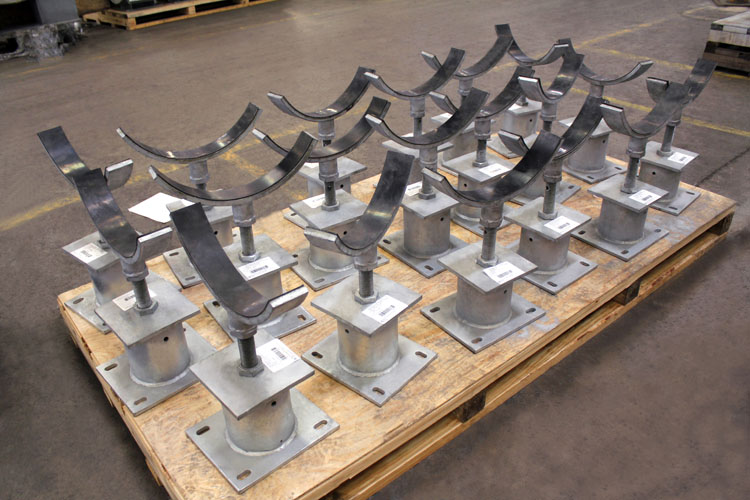
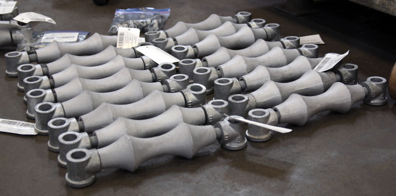
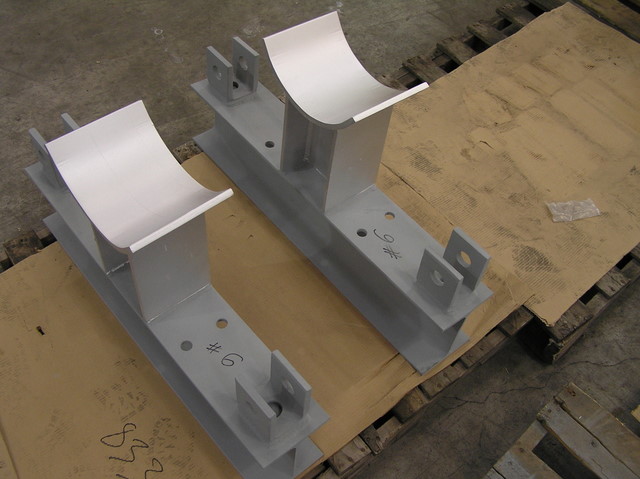
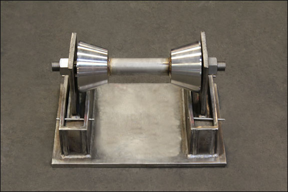
Fig. 46: Adjustable Pipe Saddle Support
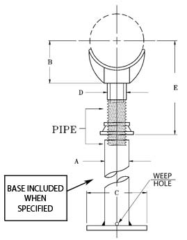
MATERIAL: Carbon steel saddle, locknut nipple, and special cast iron reducer, assembled. Base included when specified.
SERVICE: Stanchion type support where vertical adjustment is required.
INSTALLATION: Adjustment is obtained by turning the lock-nut nipple, the lower end of the nipple, and coupling during adjustment.
ORDERING: Specify figure number, pipe size, description and finish.
*Max Load varies based on overall height
| PIPE SIZE | APPROX. WEIGHT lbs. per 100 | A | B | C | D | E | MAX LOAD* |
| Complete | Saddle
Only | Square | Min. | Max. |
| 2 1/2 | 900 | 480 | 2 1/2 | 3 1/2 | 9 | 1 1/2 | 8 | 13 | 2,000 |
| 3 | 920 | 500 | 2 1/2 | 3 3/4 | 9 | 1 1/2 | 8 1/4 | 13 1/4 | 2,000 |
| 3 1/2 | 940 | 520 | 2 1/2 | 4 | 9 | 1 1/2 | 8 1/2 | 13 1/2 | 2,000 |
| 4 | 1500 | 760 | 3 | 4 1/4 | 9 | 2 1/2 | 9 1/4 | 14 | 3,800 |
| 5 | 1665 | 925 | 3 | 4 7/8 | 9 | 2 1/2 | 10 | 14 3/4 | 3,800 |
| 6 | 1765 | 1025 | 3 | 5 1/2 | 9 | 2 1/2 | 10 1/2 | 15 1/4 | 3,800 |
| 8 | 2020 | 1280 | 3 | 6 7/8 | 9 | 2 1/2 | 11 3/4 | 16 1/2 | 3,800 |
| 10 | 2515 | 1775 | 3 | 8 1/2 | 9 | 2 1/2 | 13 1/2 | 18 1/4 | 3,800 |
| 12 | 2900 | 2160 | 3 | 9 15/16 | 9 | 2 1/2 | 15 | 19 3/4 | 3,800 |
| 14 | 4920 | 3800 | 4 | 10 15/16 | 11 | 3 | 16 1/4 | 20 3/4 | 5,300 |
| 16 | 5320 | 4200 | 4 | 12 3/8 | 11 | 3 | 17 3/4 | 22 1/4 | 5,300 |
| 18 | 7080 | 5100 | 6 | 13 7/8 | 13 1/2 | 3 1/2 | 19 1/2 | 24 | 6,700 |
| 20 | 10480 | 8500 | 6 | 15 3/8 | 13 1/2 | 3 1/2 | 21 | 25 1/2 | 6,700 |
| 24 | 13000 | 11000 | 6 | 17 15/16 | 13 1/2 | 4 | 23 3/4 | 28 1/4 | 7,300 |
| 30 | 17000 | 15000 | 6 | 21 5/16 | 13 1/2 | 4 | 27 | 31 1/2 | 7,300 |
| 32 | 18100 | 16100 | 6 | 22 1/2 | 13 1/2 | 4 | 28 1/4 | 32 3/4 | 7,300 |
| 36 | 24900 | 22900 | 6 | 24 1/2 | 13 1/2 | 4 | 30 1/4 | 34 3/4 | 7,300 |
Download PDF
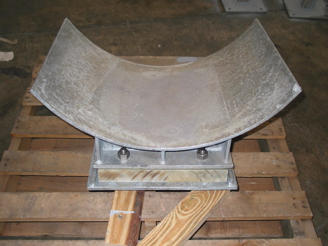
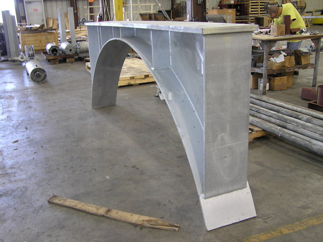
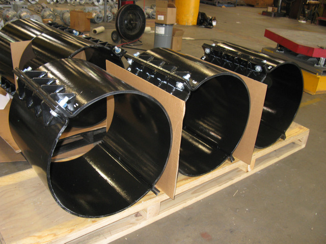
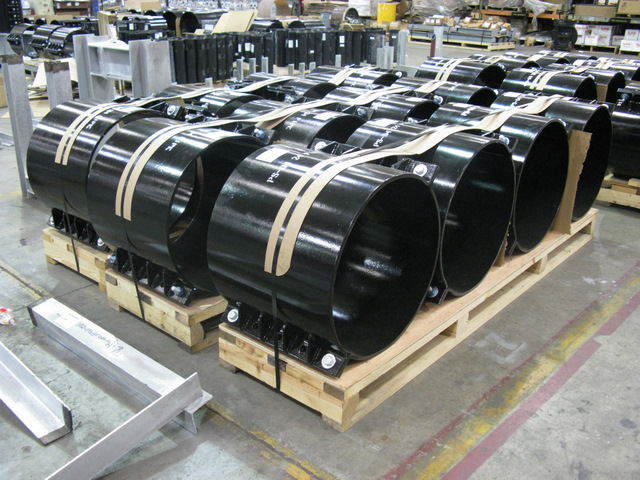
Fig. 48: Pipe Saddle Support with U-Bolt
MATERIAL: Carbon steel stanchion saddle with steel U-Bolt and nuts.
INSTALLATION:
1. Slip saddle base into riser pipe.
2. If riser pipe and flange are used, flange is drilled for bolting to steel beam or floor.
3. Yoke is attached to saddle after pipe is in place.
ORDERING: Specify figure number, pipe size, description, material and finish.
| PIPE SIZE | APPROX. WEIGHT (lbs. per 100) | A | B | MAX LOAD |
| 4 | 1075 | 3 | 4 3/16 | 3,800 |
| 5 | 1210 | 3 | 4 13/16 | 3,800 |
| 6 | 1270 | 3 | 5 7/16 | 3,800 |
| 8 | 2130 | 3 | 6 15/16 | 3,800 |
| 10 | 2570 | 3 | 8 7/16 | 3,800 |
| 12 | 3120 | 3 | 9 15/16 | 3,800 |
| 14 | 5000 | 4 | 10 15/16 | 5,300 |
| 16 | 5700 | 4 | 12 3/8 | 5,300 |
| 18 | 6400 | 4 | 13 7/8 | 6,700 |
| 20 | 11350 | 6 | 15 3/8 | 6,700 |
| 24 | 13700 | 6 | 17 15/16 | 7,300 |
| 30 | 14650 | 6 | 19 1/8 | 7,300 |
| 32 | 17400 | 8 | 21 5/16 | 7,300 |
| 36 | 26800 | 8 | 24 1/2 | 7,300 |
Download PDF
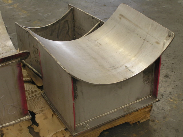
Fig. 183: Pipe Insulation Protection Shield
MATERIAL: Carbon steel
FINISH: Galvanized and black
SIZE RANGE: For use with ½” thru 24” pipe with insulation thickness ½”, 3/4”, 1”, 1 ½” and 2”.
SERVICE: Recommended for outside of foam or fiber glass insulation to preclude crushing of insulation without breaking the vapor barrier.
APPROVALS: Complies with Federal Specification WW-H-171E (Type 41) and Manufacturers Standardization Society SP-69 (Type 40).
ORDERING: Specify figure number, pipe size, description, insulation thickness and finish.
Shield Size Selection Table
Insulation Thickness (in.) |
| SIZE | 1/2 | 3/4 | 1 | 1-1/2 | 2 |
| 1/2 | 1A | 1A | — | — | — |
| 3/4 | 1A | 1A | 2A | 4A | 6A |
| 1 | 1A | 2A | 3A | 5A | 7A |
| 1 1/4 | 2A | 3A | 3A | 6A | 7A |
| 1 1/2 | 2A | 3A | 4A | 6A | 7A |
| 2 | 3A | 4A | 5A | 7A | 8A |
| 2 1/2 | 4A | 5A | 6A | 7A | 8A |
| 3 | 5A | 6A | 7A | 8A | 9A |
| 3 1/2 | — | — | 8A | 9A | 10A |
| 4 | — | — | 8A | 9A | 10A |
| 5 | — | — | 9B | 10B | 11B |
| 6 | — | — | 10B | 11B | 12B |
| 8 | — | — | — | 13C | 14C |
| 10 | — | — | 14C | 15C | 16C |
| 12 | — | — | 16C | 17C | 18C |
| 14 | — | — | 17C | 18C | 19C |
| 16 | — | — | 19C | 20C | 21C |
| 18 | — | — | 21C | 22C | 23C |
| 20 | — | — | 23C | 24C | 25C |
| 24 | — | — | 26C | 27C | 28C |
| | | SHIELD DIMENSION |
| SHIELD SIZE | STOCK SIZE (GAGE ) | APPROX. WEIGHT each | LENGTH L | RADIUS R |
| X1A | 18 | 0.54 | 12 | 0.95 |
| 1A | 18 | 0.69 | 12 | 1.19 |
| 2A | 18 | 0.84 | 12 | 1.44 |
| 3A | 18 | 0.99 | 12 | 1.75 |
| 4A | 18 | 1.1 | 12 | 2.00 |
| 5A | 18 | 1.3 | 12 | 2.25 |
| 6A | 18 | 1.4 | 12 | 2.50 |
| 7A | 18 | 1.6 | 12 | 2.78 |
| 8A | 16 | 1.9 | 12 | 3.32 |
| 9A | 16 | 2.7 | 12 | 3.82 |
| 10A | 16 | 3.1 | 12 | 4.32 |
| 9B | 16 | 4.0 | 18 | 3.82 |
| 10B | 16 | 4.6 | 18 | 4.32 |
| 11B | 16 | 5.1 | 18 | 4.82 |
| 12B | 16 | 5.6 | 18 | 5.38 |
| 13C | 14 | 10.2 | 24 | 5.88 |
| 14C | 14 | 11.1 | 24 | 6.38 |
| 15C | 14 | 11.9 | 24 | 7.00 |
| 16C | 14 | 12.7 | 24 | 7.50 |
| 17C | 14 | 13.6 | 24 | 8.00 |
| 18C | 14 | 14.5 | 24 | 8.50 |
| 19C | 12 | 21.2 | 24 | 9.00 |
| 20C | 12 | 22.4 | 24 | 9.50 |
| 21C | 12 | 23.6 | 24 | 10.00 |
| 22C | 12 | 24.8 | 24 | 10.50 |
| 23C | 12 | 25.9 | 24 | 11.00 |
| 24C | 12 | 27.1 | 24 | 11.50 |
| 25C | 12 | 28.3 | 24 | 12.00 |
| 26C | 12 | 31.0 | 24 | 13.00 |
| 27C | 12 | 31.8 | 24 | 13.50 |
| 28C | 12 | 33.0 | 24 | 14.00 |
Download PDF
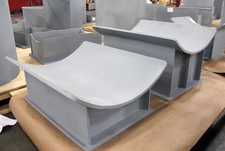
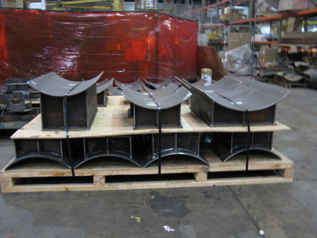
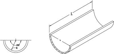
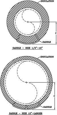
Fig. 184: Pipe Covering Saddle for 1″ Insulation

FINISH: Black, galvanized, or painted.
SERVICE : Designed to keep insulation from crushing and to reduce heat losses.
ORDERING: Specify figure number, pipe size, description, insulation thickness and finish.
NOTE: All saddles are 12” long with the side edges turned up.
| FIG. 184 - 1″ INSULATION |
| PIPE SIZE | MAX. RECOM. LOAD | APPROX. WEIGHT (lb. per 100) | COVERING THK. | C |
| 3/4 | 1200 | 141 | 7/8 | 1 9/16 |
| 1 | 1200 | 141 | 1 1/16 | 1 7/8 |
| 1 1/4 | 1200 | 141 | 7/8 | 1 7/8 |
| 1 1/2 | 1200 | 151 | 1 | 2 1/8 |
| 2 | 1200 | 167 | 1 1/16 | 2 3/8 |
| 2 1/2 | 1200 | 167 | 1 1/16 | 2 5/8 |
| 3 | 1200 | 188 | 1 | 2 15/16 |
| 3 1/2 | 1200 | 228 | 1 1/4 | 3 7/16 |
| 4 | 1200 | 228 | 1 1/16 | 3 7/16 |
| 5 | 1200 | 228 | 1 | 3 15/16 |
| 6 | 1800 | 378 | 1 | 4 1/2 |
Download PDF
Fig. 185: Pipe Covering Saddle for 1 1/2″ Insulation
FINISH: Black, galvanized, or painted.
SERVICE: Designed to keep insulation from crushing and to reduce heat losses.
ORDERING: Specify figure number, pipe size, description, insulation thickness and finish.
NOTE: All saddles are 12” long with the side edges turned up.
| FIG. 185 - 1 1/2″ INSULATION |
| PIPE SIZE | MAX. RECOM. LOAD | APPROX. WEIGHT per 100 | COVERING THK. | C |
| 3/4 | 1200 | 210 | 1 7/16 | 2 1/8 |
| 1 | 1200 | 210 | 1 9/16 | 2 3/8 |
| 1 1/4 | 1200 | 210 | 1 5/8 | 2 5/8 |
| 1 1/2 | 1200 | 210 | 1 1/2 | 2 5/8 |
| 2 | 1200 | 234 | 1 9/16 | 2 15/16 |
| 2 1/2 | 1200 | 276 | 1 7/8 | 3 7/16 |
| 3 | 1200 | 276 | 1 9/16 | 3 7/16 |
| 3 1/2 | 1200 | 321 | 1 13/16 | 3 15/16 |
| 4 | 1200 | 321 | 1 9/16 | 3 15/16 |
| 5 | 1200 | 321 | 1 1/2 | 4 7/16 |
| 6 | 1800 | 442 | 1 1/2 | 5 |
| 8 | 5000 | 581 | 1 1/2 | 6 1/8 |
| 10 | 5000 | 581 | 1 9/16 | 7 1/4 |
| 12 | 5000 | 781 | 1 9/16 | 8 1/4 |
| 14 | 5000 | 781 | 1 1/2 | 8 3/4 |
| 16 | 5000 | 844 | 1 1/2 | 9 3/4 |
| 18 | 5000 | 912 | 1 1/2 | 10 3/4 |
| 20 | 7200 | 1044 | 1 1/2 | 11 7/8 |
| 24 | 7200 | 1231 | 1 1/2 | 13 7/8 |
| 30 | 7200 | 1333 | 1 1/2 | 16 7/8 |
| 36 | 7200 | 1803 | 1 1/2 | 19 7/8 |
Download PDF
Fig. 186: Pipe Covering Saddle for 2″ Insulation

FINISH: Black, galvanized, or painted.
SERVICE: Designed to keep insulation from crushing and to reduce heat losses.
ORDERING: Specify figure number, pipe size, description, insulation thickness and finish.
NOTE: All saddles are 12” long with the side edges turned up.
| FIG. 186 - 2″ INSULATION |
| PIPE SIZE | MAX. RECOM. LOAD | APPROX. WEIGHT per 100 | COVERING THK. | C |
| 3/4 | 1200 | 276 | 1 7/8 | 2 5/8 |
| 1 | 1200 | 276 | 2 1/8 | 2 15/16 |
| 1 1/4 | 1200 | 276 | 1 15/16 | 2 15/16 |
| 1 1/2 | 1800 | 318 | 2 5/16 | 3 1/2 |
| 2 | 1800 | 319 | 2 1/8 | 3 1/2 |
| 2 1/2 | 1800 | 319 | 2 5/16 | 4 |
| 3 | 1800 | 358 | 2 1/16 | 4 |
| 3 1/2 | 1800 | 358 | 2 1/4 | 4 1/2 |
| 4 | 1800 | 358 | 2 1/16 | 4 1/2 |
| 5 | 1800 | 358 | 2 | 5 |
| 6 | 1800 | 573 | 2 | 5 9/16 |
| 8 | 1800 | 634 | 2 | 6 9/16 |
| 10 | 5000 | 765 | 2 1/16 | 7 3/4 |
| 12 | 5000 | 988 | 2 1/16 | 8 3/4 |
| 14 | 5000 | 988 | 2 | 9 1/4 |
| 16 | 5000 | 1040 | 2 | 10 1/4 |
| 18 | 7200 | 1040 | 2 | 11 3/8 |
| 20 | 7200 | 1161 | 2 | 12 3/8 |
| 24 | 7200 | 1335 | 2 | 14 3/8 |
| 30 | 7200 | 1408 | 2 | 17 3/8 |
| 36 | 7200 | 1893 | 2 | 20 3/8 |
Download PDF
Fig. 187: Pipe Covering Saddle for 2 1/2″ Insulation

FINISH: Black , galvanized, or painted.
SERVICE: Designed to keep insulation from crushing and to reduce heat losses.
ORDERING: Specify figure number, pipe size, description, insulation thickness and finish.
NOTE: All saddles are 12” long with the side edges turned up.
| FIG. 187 - 2 1/2″ INSULATION |
| PIPE SIZE | MAX. RECOM. LOAD | APPROX. WEIGHT (lb. per 100) | COVERING THK. | C |
| 1 1/4 | 1200 | 361 | 2 7/16 | 3 7/16 |
| 1 1/2 | 1800 | 361 | 2 13/16 | 4 |
| 2 | 1800 | 361 | 2 5/8 | 4 |
| 2 1/2 | 1800 | 406 | 2 7/8 | 4 1/2 |
| 3 | 1800 | 406 | 2 9/16 | 4 1/2 |
| 3 1/2 | 1800 | 446 | 2 3/4 | 5 |
| 4 | 1800 | 446 | 2 9/16 | 5 |
| 5 | 1800 | 446 | 2 9/16 | 5 9/16 |
| 6 | 1800 | 651 | 2 1/2 | 6 1/16 |
| 8 | 1800 | 721 | 2 11/16 | 7 3/16 |
| 10 | 5000 | 820 | 2 9/16 | 8 1/4 |
| 12 | 5000 | 1045 | 2 5/8 | 9 1/4 |
| 14 | 5000 | 1045 | 2 1/2 | 9 3/4 |
| 16 | 7200 | 1107 | 2 1/2 | 10 7/8 |
| 18 | 7200 | 1239 | 2 1/2 | 11 7/8 |
| 20 | 7200 | 1239 | 2 1/2 | 12 7/8 |
| 24 | 7200 | 1434 | 2 1/2 | 14 7/8 |
| 30 | 7200 | 1999 | 2 1/2 | 17 7/8 |
| 36 | 7200 | 2020 | 2 1/2 | 20 7/8 |
Download PDF
Fig. 188: Pipe Covering Saddle for 3″ Insulation

FINISH: Black , galvanized, or painted.
SERVICE: Designed to keep insulation from crushing and to reduce heat losses.
ORDERING: Specify figure number, pipe size, description, insulation thickness and finish.
NOTE: All saddles are 12” long with the side edges turned up.
| FIG. 188 - 3″ INSULATION |
| PIPE SIZE | MAX. RECOM. LOAD | APPROX. WEIGHT (lb. per 100) | COVERING THK. | C |
| 2 | 1800 | 449 | 3 1/8 | 4 1/2 |
| 2 1/2 | 1800 | 449 | 3 3/8 | 5 |
| 3 | 1800 | 491 | 3 1/16 | 5 |
| 3 1/2 | 1800 | 491 | 3 5/16 | 5 9/16 |
| 4 | 1800 | 491 | 3 1/16 | 5 9/16 |
| 5 | 1800 | 491 | 3 1/16 | 6 1/16 |
| 6 | 1800 | 773 | 3 | 6 9/16 |
| 8 | 1800 | 773 | 3 1/8 | 7 11/16 |
| 10 | 5000 | 884 | 3 1/16 | 8 3/4 |
| 12 | 5000 | 1135 | 3 1/16 | 9 3/4 |
| 14 | 5000 | 1135 | 3 | 10 1/4 |
| 16 | 7200 | 1330 | 3 | 11 3/8 |
| 18 | 7200 | 1330 | 3 | 12 3/8 |
| 20 | 7200 | 1342 | 3 | 13 3/8 |
| 24 | 7200 | 2034 | 3 | 15 3/8 |
| 30 | 7200 | 2137 | 3 | 18 3/8 |
| 36 | 7200 | 2158 | 3 | 21 3/8 |
Download PDF
Fig. 189: Pipe Covering Saddle for 4″ Insulation
FINISH: Black , galvanized, or painted.
SERVICE: Designed to keep insulation from crushing and to reduce heat losses.
ORDERING: Specify figure number, pipe size, description, insulation thickness and finish.
NOTE: All saddles are 12” long with the side edges turned up.
| FIG. 189 - 4″ INSULATION |
| PIPE SIZE | MAX. RECOM. LOAD | APPROX. WEIGHT (lb. per 100) | COVERING THK. | C |
| 4 | 1800 | 611 | 4 1/16 | 6 9/16 |
| 5 | 1800 | 611 | 4 3/16 | 7 3/16 |
| 6 | 1800 | 1020 | 4 1/8 | 7 11/16 |
| 8 | 1800 | 1020 | 4 3/16 | 8 11/16 |
| 10 | 5000 | 1083 | 4 1/16 | 9 3/4 |
| 12 | 5000 | 1398 | 4 1/8 | 10 3/4 |
| 14 | 5000 | 1398 | 4 | 11 1/4 |
| 16 | 7200 | 1530 | 4 | 12 3/8 |
| 18 | 7200 | 1530 | 4 | 13 3/8 |
| 20 | 7200 | 2279 | 4 | 14 3/8 |
| 24 | 7200 | 2305 | 4 | 16 3/8 |
| 30 | 7200 | 2396 | 4 | 19 3/8 |
| 36 | 7200 | 2413 | 4 | 22 3/8 |
Download PDF
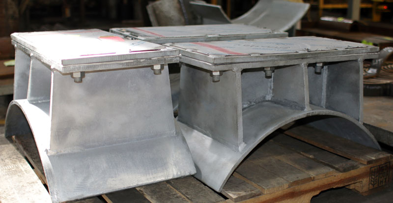
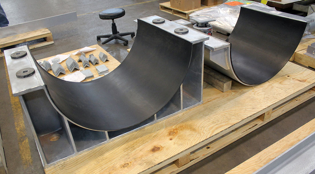
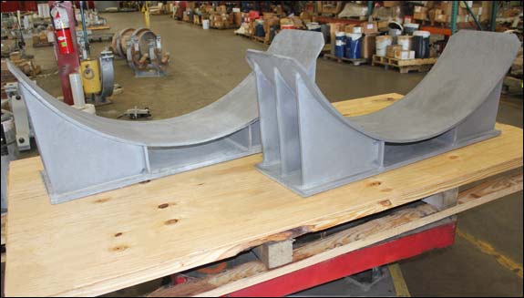
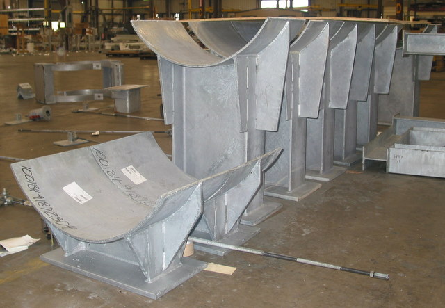
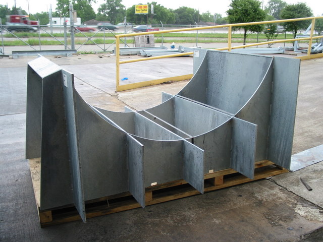
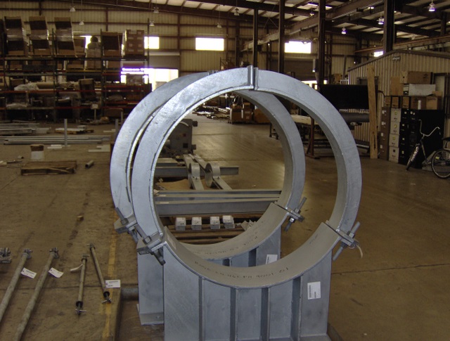
Fig. 2000: Heavy Duty Pipe Saddles
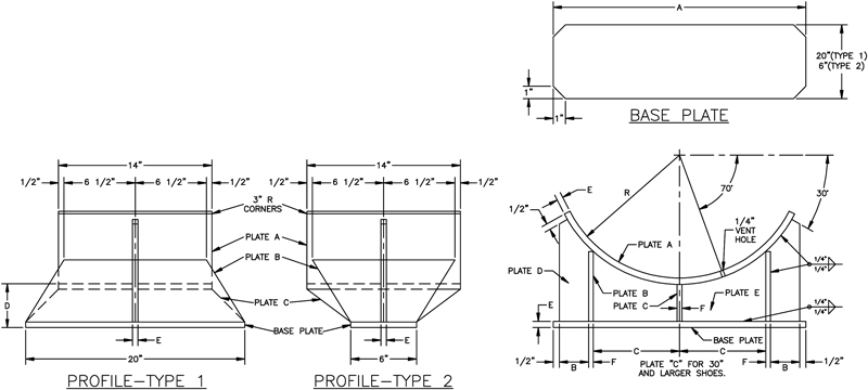
NOTE:
1. Tolerances: R=1%-0
Other Dimension – 1/16, Except Plate Thickness – 1/32 Angle – 1 1/4 Deg.
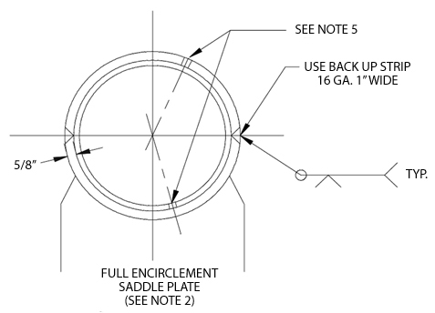
2. Full Encirclement Saddle Plates shall be used on all cross-country pipelines, on Grade X-46 or higher strength pipe, and on all station pipework designed to operate at or in excess of 90% of Min. Specified yield strength. Segmental Saddle Plates shall be used on station pipework designed to operate at less than 50% of min. yield strength.
3. For maximum spans of pipelines using saddles use Standard Engineering Practice.
4. Pipe Support of Sleeper Under the Saddle shall be designed to accommodate full axial movement of the pipeline and saddle.
5. Vent hole 1/4 to be drilled in each segment of saddle.
HOW TO ORDER: Specify figure number, pipe size, and description.
| PIPE SIZE | RADIUS | DIMENSIONS | APPROX.
WEIGHT lbs. |
R
| A | B | C | D
| E
| F | Type 1 | Type 2 |
20
| 10
| 20 1/2
| 2 3/8
| 7
| 4
| 1/2
| 3/8
| 165
| 90
|
22
| 11
| 22
| 2 5/8
| 7 1/2
| 4
| 1/2
| 3/8
| 185
| 100
|
24
| 12
| 23 1/2
| 2 7/8
| 8
| 4
| 1/2
| 3/8
| 195
| 105
|
26
| 13
| 25 1/2
| 3 3/8
| 8 1/2
| 4
| 1/2
| 3/8
| 210
| 110
|
28
| 14
| 27
| 3 5/8
| 9
| 4
| 1/2
| 3/8
| 230
| 120
|
30
| 15
| 29
| 4
| 9 1/2
| 4
| 5/8
| 1/2
| 315
| 175
|
32
| 16
| 31
| 4 1/2
| 10
| 4
| 5/8
| 1/2
| 330
| 190
|
34
| 17
| 32
| 5
| 10
| 4
| 5/8
| 1/2
| 355
| 200
|
36
| 18
| 34
| 5
| 11
| 4
| 5/8
| 1/2
| 375
| 210
|
38
| 19
| 36
| 6
| 11
| 4
| 5/8
| 1/2
| 395
| 220
|
40
| 20
| 38
| 6
| 12
| 4
| 5/8
| 1/2
| 420
| 235
|
42
| 21
| 40
| 6
| 13
| 4
| 5/8
| 1/2
| 440
| 250
|
48
| 24
| 46
| 6
| 16
| 4
| 5/8
| 1/2
| 510
| 285
|
54
| 27
| 52
| 7
| 19
| 4
| 5/8
| 1/2
| 575
| 320
|
60
| 30
| 58
| 8
| 20
| 4
| 5/8
| 1/2
| 625
| 360
|