July 2002 News

July 4, 2002

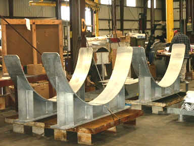
PT&P Custom Designs and Fabricates Big Ton Springs Equipped with Lifting Lugs
Big Ton Springs
Big Ton Springs

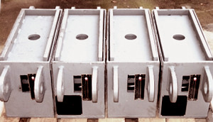
Piping Technology & Products, Inc. specially designed and fabricated big ton springs equipped with side lifting lugs to support piping of a 102-megawatt, refinery co-generation power plant in California.

Under typical circumstances, this type of job application would utilize variable spring hangers, but because of the restricted space, the hangers’ size would be too small to support a hot load of 19,068 lbs and cold load of 17,212 lbs.  In order to satisfy both the required loads and space, PT&P engineers designed and fabricated figure 500 big ton springs equipped with side lifting lugs. The lifting lugs were attached to allow the big ton to suspend as a variable spring would in the field.

The big ton springs are comprised of A-36 carbon steel and built at 13″x 23″x 9-1/2″ with a downward travel of .232″. The job was completed within two days to meet the customer’s quick turn requirements.

Introducing PT&P’s Maintenance Free Slide Plates, Bronzphites®

Piping Technology and Products is a supplier of maintenance free slide bearing plates, Bronzphite®, whose high strength bearings and impregnated graphite, together create a concoction ideal for maintaining excellent wear resistance and durability under severe operating conditions. PT&P has supplied Bronzphite® for a number of companies in the oil, gas and power industry.

Read More

March 2002 News

March 4, 2002

PT&P Utilizes 3D-Modeling Technology to Design Pipe Supports for a 750MW Power Plant

3D-Design Clamp
3D-Design
Pipe Clamps
Pipe Supports on Shipping Floor

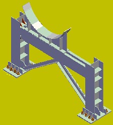
Piping Technology & Products, Inc. recently designed and fabricated 9 pipe supports with loads up to 75,000 lbs. for a 750MW power plant in Alabama. After extensive engineering hours and structure analysis, PT&P’s engineering department produced a detailed design and 3-D model for the supports that would allow them to run electronic interface checks. The supports are to support the cooling towers’ circulatory water system at the power plant. Six of the 9 supports were designed for a 60” line and 50,000 lb. load, and the remaining 3 were designed for a 78” line and 75,000 lbs. of load.

Furnace Springs Versus Standard Springs The major differences between standard springs and furnace springs are their construction and intended use. Furnace springs operate in much the same way as other variable spring supports. They are designed to support the pipe and tubes that are subject to vertical thermal movement. The design changes come about because, furnace springs are exposed to extreme temperatures.

FURNACE SPRINGS STANDARD SPRINGS
COATINGS Red oxide primer in order to aviod potential hazards when exposed to high temperatures Hot dipped galvanized which tends to melt the zinc coating. Molten zinc can damage surrounding pipe and equipment.
CONSTRUCTION
Unique to its application and intended use
Welded design for housing assembly
Centers the spring coils within the housing and accommodates lug attachments
Interchangeable
Bolted configuration for the housing
DESIGN Spring used as a means to determine the loading of the catalyst tubes
Read More

August 2001 News

August 15, 2001

Breaking News: NEW pipingtech.com

On August 06, 2001, PT&P launched its new website. pipingtech.com now has a new design and structure.  We hope you will find it simpler and more intuitive to find what you are searching for. Browse through its many pages and explore the new features that we have added:

Features:

  • Menu bar with mouse over features. Allows you to view the different categories under that section before you click on it.
  • In the news side menu bar- Allows you to view and select PT&P’s current press releases
  • A new products section that is categorized by type of product.
  • Product testing section – Describes the type of testing we do, the procedure and its purpose
  • Highlights section – Highlights upcoming events, stories, additions, etc.
  • Emergency/Quick Turn Request Form
  • Easily accessible catalog request form
Read More

June 2001 News: Issue 1

June 4, 2001

PT&P Verifies New Designs for LNG Phenolic Base Support with Load Testing

Load Testing
Load Testing

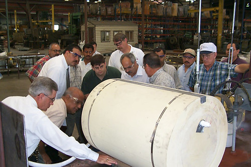
Piping Technology & Products, Inc. performs thorough product testing to verify new designs to a LNG Laminated Phenolic base support for an E&C company located in Houston, Texas. In order to determine the failure loads for a 30″ diameter, pre-insulated shoes and a 6″ diameter Laminated Phenolic base support respectively, PT&P performed lateral-load and axial load tests. The load tests performed ensure the pre-insulated pipe shoes can safely sustain the specified design load. The insulated shoes tested for the E&C company will be in service in 2001 at Atlantic LNG, where they will be used to support the liquid nitrogen gas (LNG) lines.

Big Ton Springs Installation Guide
Big Ton 1. Measure the existing installed load setting height to make sure that the big ton spring will fit tightly into the space provided. Shim from below as needed to ensure proper fit.
2. Place the big ton spring in the designated location, making sure that all required slide plates, shims, or auxiliary steel are in their proper positions.
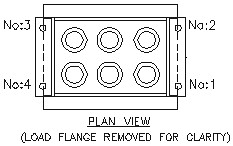
3. Travel stop bolts can be released after all testing has been done. The travel stops are painted red and located on each end of the big ton spring. Follow the steps below to release the travel bolt stops. Please refer to the drawings to the left.
(a) Turn the nut on travel stop bolt No. 1 one-half turn; repeat on bolts 2 through 4.
(b) Repeat in this sequential order until the load is released. The load has now been transferred to whatever the big ton spring is supporting.
4. CAUTION: Be sure that the nuts on the travel stop bolts are backed off enough to accommodate the appropriate travel (Example: 1 inch of travel – the nuts should be backed off by 2 inches from the bottom of the travel stop plate.)
5. At this time the Lifting Eye Bolts may be removed.

Tension Systems
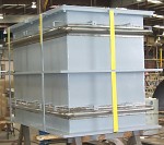
In some cases, a straight line system of axial bellows anchors and guides is not practical or desired; or there is no reasonable way/ place to anchor the bellows thrust loads. In such cases self restrained bellows assemblies may be used, such as the double hinge restrained bellows shown below. Thermal expansion (or contraction) in the long pipe is absorbed by an offset deflection of the double hinge assembly. Bellows thrust load is carried by hinge bars, gimbals, tie rods or other such devices; hence normal tension is maintained in the pipe system and main anchors and full lateral restraint guides are unnecessary.

Read More

April 2001 News

April 10, 2001

PT&P Manufactures Custom Designed Embed Plates for Gold Mine in Cajamarca, Peru
Piping Technology & Products, Inc., designed and manufactured 150 special embed plate pieces for Latin America’s largest gold producer. This project involved the production of one hundred fifty, 93″ x 27″ x 1″ embed plates which required the use of 80,000 pounds of steel and anchors. The custom designed, carbon steel, embed plates are to provide stability for the feed openings of four mineshaft reclaim tunnels and are scheduled to be put to use immediately.

Custom Embed Plates for Gold Mine in Cajamarca, Peru

How to Avoid Pipe Stress
What is Pipe Stress?
“Pipe Stress” refers to piping flexibility analysis.

High Stress Locations on Pipes
High stress areas generally occur at piping elbows, tees and other branch connections. The B 31.3 Piping Code provides stress intensification factors for such locations. Computer piping programs generally do piping flexibility analysis for those other than very simple systems.

Signs of Pipe Stress
An overstressed system could fail by fatigue, leading to a crack, buckling of the elbows, or overload on equipment nozzles.

How to Reduce Pipe Stress
High stress should be uncovered in the design stage. However, existing systems can be checked for incipient cracks by x-ray, ultrasound, acoustic emission or dye penetrant. Also, rerouting the pipe can provide more flexibility and sometimes reduce high stress. When rerouting is impossible or not practical, then pipe stress can be reduced significantly by adding Bellows Expansion Joints. Any sections of the pipe showing cracks must be replaced.

Product of the Month

Transition Piece
Transition Piece
Transition Piece
Transition Piece

(at left)47.25″ I.D. x 23.625″ I.D. 5A516-70 Transition Pieces w/ 5A36 stiffner for ethylene plant in Saudia Arabia. (at right)47.25″ I.D. Universal Expansion Joint w/ SB443 round corners bellows, and SA516-70 flanges for ethylene plant in Saudia Arabia.

Read More

Recent Photos From the Shop

November 4, 1998
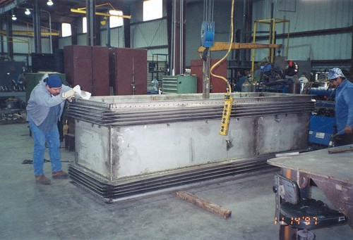
Stainless Steel Rectangular Expansion Joint
Stainless Steel Rectangular Expansion Joint for Machinery Exhaust Application
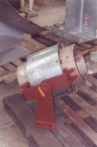
Gimbal Expansion Joint
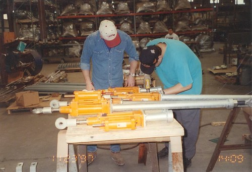
Hydraulic Snubbers
48" Stroke Hydraulic Snubbers
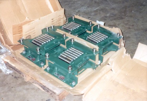
Roller Supports
X-Z Roller Supports for Big Ton Springs (20,000 lbs, 8" travel) for Pressure Vessels
Read More

PT&P Acquires Mobile Test Facility for Snubbers

October 31, 1998

In addition to the snubber test equipment obtained from Basic Engineers, PT&P has purchased a mobile snubber test facility from Commonwealth Edison, an electric utility in Illinois. The mobile snubber test trailer was in use at ComEd’s La Salle Nuclear facility.

This snubber test system is installed in a large truck trailer which was specifically designed to house a mobile test facility. The trailer is 47.5 feet long and is climate controlled with both heat and air conditioning. It has a one-ton crane that runs the length of the trailer and can be extended an additional 8 feet for loading and unloading snubbers. It also includes a small office.

The snubber test trailer contains test benches with a test capacity of 135,000 lbs. PT&P plans to begin providing field testing service to customers using this mobile facility.

Do you require snubbers for an upcoming project? Request a quote today!

request-a-quote

Read More

PT&P signed for Power Project in Puerto Rico

October 24, 1998

PT&P has a contract to provide the fabricated pipe supports and the cold shoes on a power plant in Puerto Rico. Imported liquid natural gas will be the primary fuel for the plant.  PT&P cold shoes will be important to support the piping from the LNG storage tanks to the power plant. PT&P has worked on power projects in Rhode Island and Beaumont, Texas. Currently, PT&P is working on power projects in China, Malaysia and various sites in the United States.

Basic Engineers Auction Yields Manufacturing Machinery
A supplier of pipe supports, Basic Engineers (BE) of Johnstown, PA decided to close its business in late 1997. In May 1998, the company held an auction to liquidate BE’s manufacturing equipment.  PT&P acquired the majority of Basic Engineers’ assets, including its test equipment for snubbers.  For additional information on snubbers, please refer to our Mobility Test article.

Fall Open House Set For November 4
PT&P’s workforce of over 350 dedicated employees will welcome guests at this year’s Fall open house, from 11:30 a.m. to 3:30 p.m., Wednesday, November 4. The celebration will be at the plant: 3701 Holmes Rd. in Houston, Texas.  Those who attend will be treated to a luncheon and have the opportunity to register for door prizes including a pentium computer, golf clubs and sports bags.

Read More

PT&P Breaks Ground on Another Plant Expansion

September 20, 1998

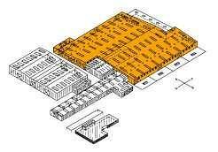
In August, PT&P broke ground on another expansion to its manufacturing facilities in Houston, Texas. The contract for another 100,000-square feet metal building was awarded several months ago. The selected vendor will provide drawings, materials and erection services.

Plant Expansion
Plant Expansion

As the illustration at left shows, this plant expansion will nearly double PT&P’s manufacturing work space. PT&P’s new building will contain machinery from its U.S. Bellows Expansion Joints Division as well as machines for PT&P’s other product lines.

PT&P added 100,000 sq. ft. of shop space two years ago. This expansion, expected to be complete by the November 4 open house, will bring total shop space to nearly 450,000 sq. ft.

Read More

PT&P Sponsors University of Houston Student Project

September 15, 1998

PT&P again sponsored a University of Houston Mechanical Engineering student design project during the Fall ’97 term. The team of Sandra Ramos, Dorsa Froutan, Irma Adame and E.J. Del Valle titled their project Deasign, Test and Modeling of Cryogenic Pipe Supports. All were Seniors enrolled in MECE 4334: Mechanical Engineering Systems Design. Similar courses are required for Industrial Engineering, Electrical and Computer Engineering students.

The U of H faculty requests companies to submit problem statements for projects they are willing to sponsor. If their project is chosen by a student team, companies designate an engineer-in-charge who helps their faculty consultant advise the students. The students prepare a written proposal defining their plan during the first four weeks and make weekly progress reports thereafter. Companies provide facilities and equipment as required. The students prepare a final written report and make an oral presentation at their campus at the end of the semester.

This team did a series of experiments both at ambient and cryogenic temperatures using pipe shoes with polyurethane (PUF) of various densities. They studied compressive strength, heat transfer rates and clamping forces required to maintain contact with a pipe under axial loading. This was the fifth project sponsored by PT&P. We thank these students for their hard work, and we wish them much success during their professional careers.

Customers Mail Back Survey Cards

Thanks to the many customers who mailed back survey cards from our Fall ’97 mailings. We received a number of good suggestions and potential topics for future technical bulletins. The statistics on four Yes or No questions are:

  • 91%: Yes, the PT&P technical bulletins are useful to their jobs.
  • 89%: Yes, their job requires use of the PT&P catalogs.
  • 99%: Yes, PT&P newsletters cover topics of interest to them.
  • 61%: No, the photos on PT&P’s annual calendars should not be changed.
Read More
Top