Sway Struts
A sway strut is a device used to restrain movement of piping in one direction while providing for movement due to thermal expansion or contraction in another direction.
Ammonia Plant
Chemical Plant
Clean Fuels
Commercial
Electric Plant
Energy Facility
Ethylene Plant
LLDPE Chemical Plant
LNG Plant
MTBE Plant
Natural Gas Combined Cycle Facility
Natural Gas Processing & Separation
Oil Refinery
Oil Sand Mine
Paper Manufacturer
See All
Piping struts,also referred to as sway struts, are devices used to restrain movement of piping in one direction while providing ...Continue Reading
More FAQs…
General Dimensions & Specifications
- Sway Strut Information
- Fig. 2110: Sway Strut with 4" of Adjustment
- Fig. 2120: Mini-Sway Strut
- Fig. 515: Sway Strut Assembly
- Fig. 516: Adjustable Sway Strut Assembly
- Fig. 2110 & 2120
- Request a Quote
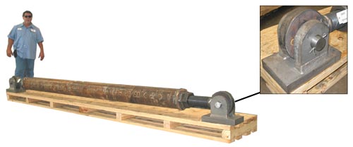
MATERIAL: Carbon steel, except for load pin, which is an Alloy.
SPECIFICATIONS:
• Manufacturer’s Standardization Society SP-58
• Manufacturer’s Standardization Society SP-69
• ANSI Code for Pressure Piping ANSI B31.1 and ANSI B31.3
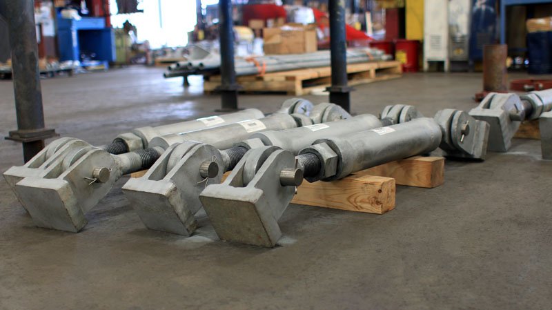
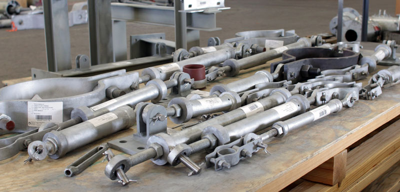
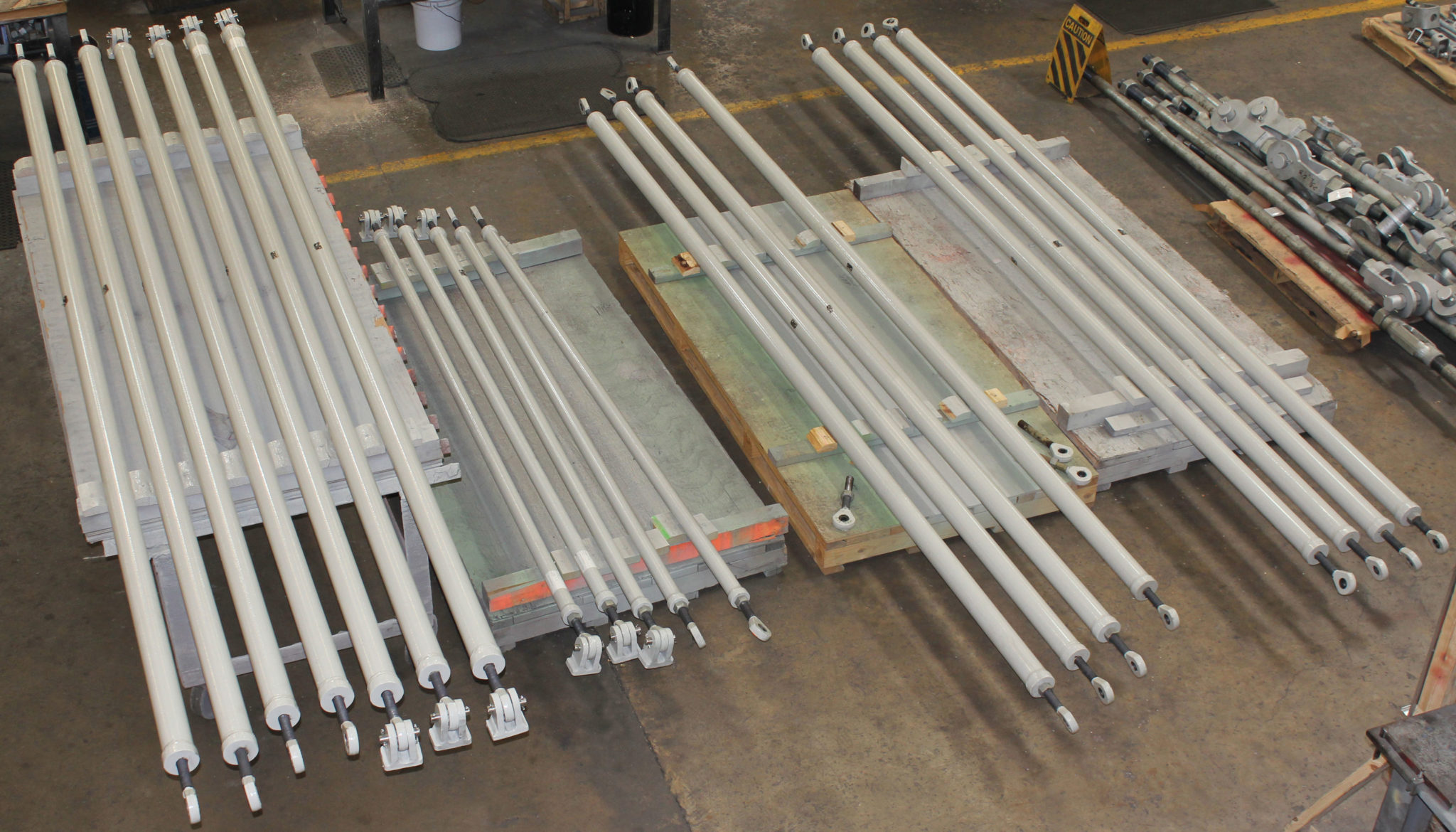
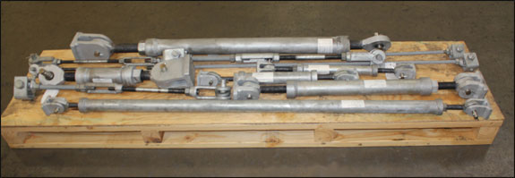
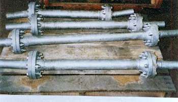
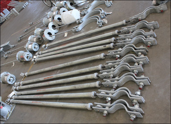
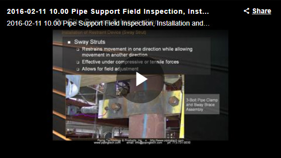
RECOMMENDED SERVICE: Used to restrain movement of piping in one direction while providing for movement due to thermal expansion or contraction in another direction.
FEATURES:
• Effective under either tensile or compressive force.
• Provides 2” to 4” of field adjustment in either direction.
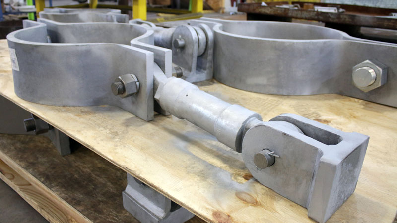
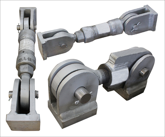
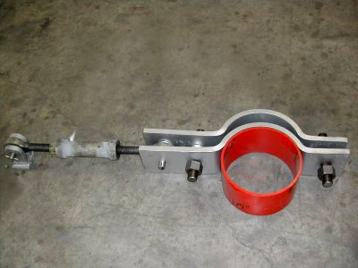
• Spherical, self-aligning ball bushing at both ends of the strut allows for plus or minus 5 degrees of angular motion or misalignment. Bushings are coated with a dry lubricant.
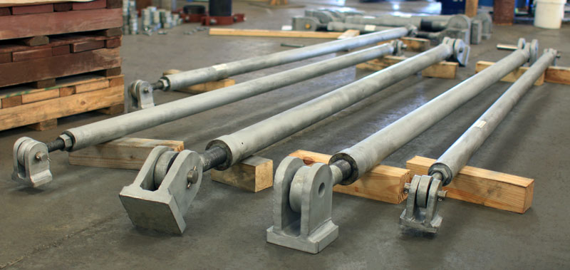
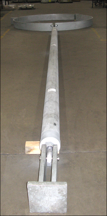
• Can be installed in any spatial orientation.
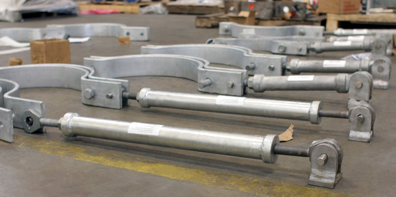
• Positive control of piping systems are allowed by tight-fitting connections.
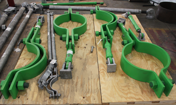
• Finished with standard primer paint or hot dip galvanizing for corrosive conditions.
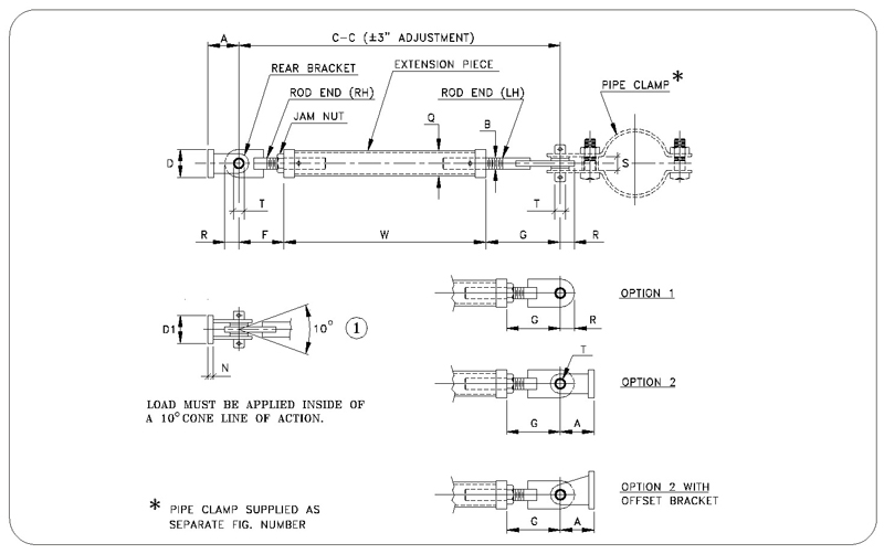
HOW TO SIZE:
1. Select size consistent with maximum load to be restrained.
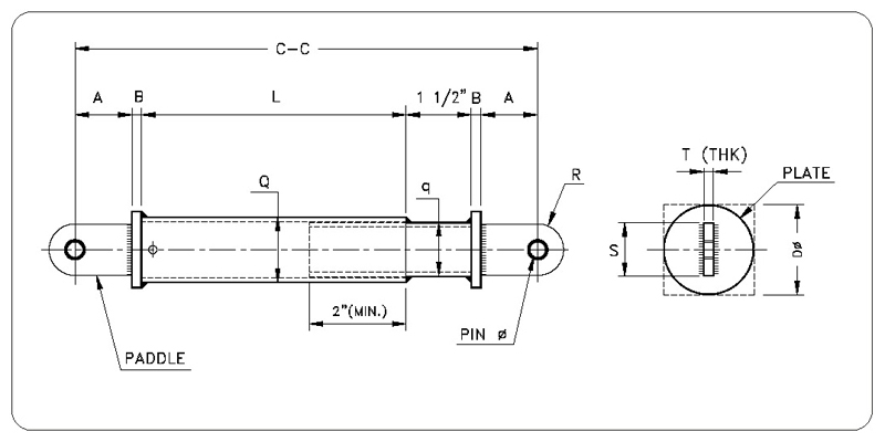
2. Determine the distance from structural steel to center of pipe and subtract from it the pipe clamp take-out and the rear bracket (dimension A) for size selected. This will give the required C-to-C dimension. Make sure that the C-to-C dimension listed for the size selected is within the specified minimum and maximum.
3. Determine the W dimension by subtracting the quantity (2 x dimension F) from the C-to-C dimension.
ORDERING: Specify figure number, assembly size, name, C-to-C dimension and option number (if other than standard configuration is required) or nominal pipe size or special O.D. The rear bracket assembly may be ordered separately.
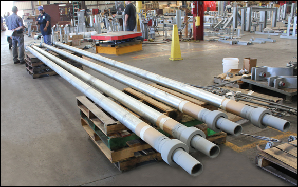
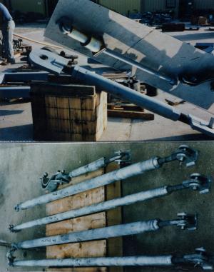
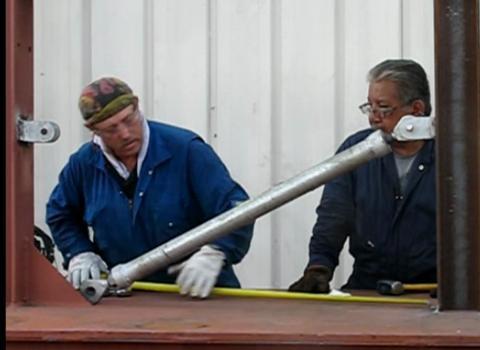
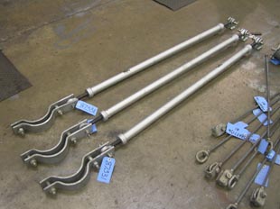
INSTALLATION: Sway strut assemblies are shipped assembled. Securely fasten bracket to structure. Attach strut rod to end bracket, make necessary adjustment in overall length, and fasten clamp to pipe. This assembly is locked by tightening the hex nuts against the extension piece.
NOTE: Rods should be visible in the sight holes at each end of the strut to assure proper thread engagement. Special lengths are available upon request.
Fig. 2110: Sway Strut with 4″ of Adjustment
NOTE: Rods should be visible in the sight holes at each end of the strut to assure proper thread engagement. Special lengths are available upon request.
* Load must not be applied outside a 10° included angle to the pipe clamp axis
ORDERING: Specify figure number, size, type, description, nominal pipe size or special O.D. and C-to-C dimension.
SIZE | LOAD lbs. | ROD END | EXT. PIECE PIPE SIZE | A | C-C | W Min. | F | D | D1 | N | R | S | T | |
Min. | Max. |
|||||||||||||
A | 650 | 3/4 | 1″ SCH.80 | 1 1/2 | 18 3/4 | 60 | 9 1/2 | 4 5/8 | 1 5/8 | 1 3/4 | 1/4 | 1 | 3/4 | 0.497 0.495 |
B | 1500 | 1 | 1 1/2″ SCH.40 | 2 3/8 | 20 1/2 | 108 | 10 | 5 1/4 | 2 1/4 | 2 7/8 | 3/8 | 1 1/8 | 1 1/8 | 0.747 0.745 |
C | 4500 | 1 | 2″ SCH.40 | 2 3/4 | 20 1/2 | 120 | 10 | 5 1/4 | 2 1/2 | 3 3/8 | 1/2 | 1 1/2 | 1 1/8 | 0.745 0.745 |
1 | 8000 | 1 1/4 | 2″ SCH.160 | 3 3/4 | 24 | 120 | 10 1/2 | 6 3/4 | 3 | 4 3/8 | 3/4 | 1 3/4 | 1 3/8 | 0.997 0.995 |
2 | 11630 | 1 1/2 | 2 1/2″ SCH.160 | 3 | 25 | 120 | 11 | 7 | 3 1/2 | 5 3/8 | 3/4 | 1 3/4 | 1 1/2 | 0.997 0.995 |
3 | 15700 | 1 3/4 | 2 1/2″ SCH.160 | 5 5/16 | 25 1/2 | 120 | 11 1/2 | 7 | 5 7/16 | 4 11/16 | 1 | 2 | 1 13/16 | 1.248 1.246 |
4 | 20700 | 2 | 3″ SCH.160 | 5 5/16 | 29 1/2 | 120 | 12 | 8 3/4 | 5 7/16 | 4 11/16 | 1 | 2 1/2 | 1 13/16 | 1.248 1.246 |
5 | 27200 | 2 1/4 | 3″ SCH.160 | 6 | 32 1/2 | 120 | 13 | 9 3/4 | 5 9/16 | 6 | 1 1/4 | 2 1/2 | 2 1/8 | 1.498 1.496 |
6 | 33500 | 2 1/2 | 4″ SCH.160 | 6 3/4 | 35 1/2 | 120 | 13 | 11 1/4 | 6 1/8 | 6 9/16 | 1 3/4 | 3 | 2 3/16 | 1.748 1.746 |
7 | 68200 | 3 | 4″ SCH.160 | 6 | 38 1/2 | 120 | 14 | 12 1/4 | 7 1/8 | 5 3/4 | 2 | 3 1/2 | 2 3/8 | 1.998 1.996 |
8 | 120000 | 4 | 6" SCH. 160 | 7 1/4 | 41 1/2 | 120 | 16 | 12 3/4 | 14 | 8 3/4 | 2 1/4 | 4 3/4 | 2 13/16 | 2.498 2.496 |
Fig. 2120: Mini-Sway Strut
ORDERING: Specify figure number, size, type, description, nominal pipe size or special O.D. and C-to-C dimension.
SIZE | LOAD | ROD END | EXT. PIECE PIPE SIZE | A | C-C (Style 1) | C-C (Style 2) | D | D1 | N | R | S | T | ||
Min. | Max. | Min. | Max. | |||||||||||
A | 650 | 3/4 | 1″ SCH.80 | 1 1/2 | 8 1/8 | 9 3/4 | 9 5/8 | 18 3/4 | 1 5/8 | 1 3/4 | 1/4 | 1 | 3/4 | 0.497 0.495 |
B | 1500 | 1 | 1 1/2″ SCH.40 | 2 3/8 | 9 3/4 | 11 1/2 | 11 1/2 | 20 1/2 | 2 1/4 | 2 7/8 | 3/8 | 1 1/8 | 1 1/8 | 0.747 0.745 |
C | 4500 | 1 | 2″ SCH.40 | 2 3/4 | 10 | 12 | 11 1/2 | 20 1/2 | 2 1/2 | 3 3/8 | 1/2 | 1 1/2 | 1 1/8 | 0.745 0.745 |
1 | 8000 | 1 1/4 | 2″ SCH.160 | 3 3/4 | 11 1/8 | 13 1/4 | 13 1/8 | 24 | 3 | 4 3/8 | 3/4 | 1 3/4 | 1 3/8 | 0.997 0.995 |
2 | 11630 | 1 1/2 | 2 1/2″ SCH.160 | 3 | 11 3/4 | 14 1/2 | 14 1/4 | 25 | 3 1/2 | 5 3/8 | 3/4 | 1 3/4 | 1 1/2 | 0.997 0.995 |
3 | 15700 | 1 3/4 | 2 1/2″ SCH.160 | 5 5/16 | 13 3/8 | 16 | 15 7/8 | 25 1/2 | 5 7/16 | 4 11/16 | 1 | 2 | 1 13/16 | 1.248 1.246 |
4 | 20700 | 2 | 3″ SCH.160 | 5 5/16 | 15 1/2 | 19 | 18 1/2 | 29 1/2 | 5 7/16 | 4 11/16 | 1 | 2 1/2 | 1 13/16 | 1.248 1.246 |
5 | 27200 | 2 1/4 | 3″ SCH.160 | 6 | 16 7/8 | 20 1/2 | 20 3/8 | 32 1/2 | 5 9/16 | 6 | 1 1/4 | 2 1/2 | 2 1/8 | 1.498 1.496 |
6 | 33500 | 2 1/2 | 4″ SCH.160 | 6 3/4 | 18 1/4 | 23 | 22 1/4 | 35 1/2 | 6 1/8 | 6 9/16 | 1 3/4 | 3 | 2 3/16 | 1.748 1.746 |
7 | 68200 | 3 | 4″ SCH.160 | 6 | 20 | 24 | 24 | 38 1/2 | 7 1/8 | 5 3/4 | 2 | 3 1/2 | 2 3/8 | 1.998 1.996 |
* All struts provided with +/- 1″ adjustment from specified C-C dimension.
Sway Strut Assembly
HOW TO ORDER: Specify figure number, assembly size, name, nominal pipe size or special O.D., clamp material (alloy or carbon steel) and dimension C-C.
SERVICE:
Used to restrain movement of piping in one direction while allowing for movement due to thermal expansion in other directions. Effective for either tensile or compressive force. Self-aligning bushings permit ±5 degrees misalignment or angular motion.
SIZE | LOAD (1) | A | B | C-C | D | D1 | F | G | N | Q | R | S | T | W MIN | |
MAX | MIN | ||||||||||||||
0 | 2,710 | 2 | 3/4 | 120 | 17 | 2 1/2 | 2 3/4 | 4 3/4 | 4 | 1/2 | 1 7/8 | 1 | 1 1/4 | 3/4 | 8 1/4 |
1 | 8,000 | 2 1/2 | 1 1/4 | 120 | 20 1/2 | 3 | 3 1/2 | 6 1/4 | 5 | 3/4 | 2 3/8 | 1 1/2 | 1 1/2 | 1 | 9 1/4 |
2 | 11,630 | 2 1/2 | 1 1/2 | 120 | 21 1/2 | 3 | 3 1/2 | 6 1/2 | 5 | 3/4 | 2 7/8 | 1 1/2 | 1 1/2 | 1 | 10 |
3 | 15,700 | 4 | 1 3/4 | 120 | 26 1/4 | 5 | 4 3/4 | 8 3/4 | 7 | 1 | 3 1/2 | 2 1/2 | 2 | 1 1/2 | 10 1/2 |
4 | 20,700 | 4 | 2 | 120 | 26 | 5 | 4 3/4 | 8 | 7 | 1 | 3 1/2 | 2 1/2 | 2 | 1 1/2 | 11 |
5 | 27,200 | 4 | 2 1/4 | 120 | 28 1/8 | 5 | 4 3/4 | 8 5/8 | 7 1/2 | 1 | 3 1/2 | 2 1/2 | 2 | 1 1/2 | 12 |
6 | 33,500 | 5 1/2 | 2 1/2 | 120 | 32 3/4 | 7 | 6 | 10 3/4 | 9 1/2 | 1 1/2 | 4 1/2 | 3 1/2 | 2 3/8 | 2 | 12 1/2 |
7 | 50,600 | 5 1/2 | 3 | 120 | 34 | 7 | 6 | 11 | 9 1/2 | 1 1/2 | 4 1/2 | 3 1/2 | 2 3/8 | 2 | 13 1/2 |
8 | 71,600 | 6 | 3 1/2 | 120 | 37 1/4 | 7 | 6 1/2 | 12 1/4 | 10 1/2 | 1 1/2 | 5 9/16 | 4 | 2 3/4 | 2 1/4 | 14 1/2 |
9 | 95,500 | 8 1/2 | 4 | 120 | 41 1/2 | 10 | 10 | 14 | 12 | 2 | 5 9/16 | 5 | 3 7/8 | 3 | 15 1/2 |
10 | 123,200 | 8 1/2 | 4 1/2 | 120 | 43 3/4 | 10 | 10 | 14 3/4 | 12 1/2 | 2 | 6 5/8 | 5 1/2 | 3 7/8 | 3 | 16 1/2 |
Fig. 516 Adjustable Sway Strut Assembly
HOW TO ORDER: Specify size, figure number, description, normal pipe size or special O.D. and C-to-C dimension.
SERVICE:
Used to restrain movement of piping in one direction while allowing for movement due to thermal expansion in other directions. Effective for either tensile or compressive force. Self-aligning bushings permit ±5 degrees misalignment or angular motion.
SIZE | MAX LOAD LB | A | B | C-C | L-L | PIN (dia.) | D (dia.) | Q (dia.) | q (dia.) | R | S | T | WEIGHT (APPROX.) | |||
MIN | MAX | MIN | MAX | C-C MIN | C-C MAX | |||||||||||
0 | 2,710 | 1 5/8 | 3/8 | 9 | 17 | 3 1/2 | 11 1/2 | 3/4 | 2 1/2 | 2.375 | 1.900 | 1 | 2 | 5/8 | 6 | 9.3 |
1 | 8,000 | 2 1/4 | 3/4 | 11 | 21 1/2 | 3 1/2 | 14 | 1 | 3 | 2.375 | 1.900 | 1 1/2 | 3 | 3/4 | 9.9 | 14.3 |
2 | 11,630 | 2 1/4 | 3/4 | 11 | 22 | 3 1/2 | 14 1/2 | 1 | 3 1/2 | 2.875 | 2.375 | 1 1/2 | 3 | 3/4 | 12.2 | 19.2 |
3 | 15,700 | 3 1/2 | 3/4 | 13 1/2 | 28 1/2 | 3 1/2 | 18 1/2 | 1 1/2 | 4 1/2 | 3.500 | 2.875 | 2 1/2 | 5 | 1 1/8 | 28.3 | 41.1 |
4 | 20,700 | 3 1/4 | 1 | 13 1/2 | 26 5/8 | 3 1/2 | 16 5/8 | 1 1/2 | 5 | 4.500 | 3.500 | 2 1/2 | 5 | 1 1/8 | 35.2 | 51.6 |
Fig. 2110 & 2120: Sway Strut Assemblies
ORDERING: Specify size, figure number, description, normal pipe size or special O.D. and C-to-C dimension.
E-TAKEOUT FOR FIG’S 2110 & 2120 SWAY STRUT ASSEMBLIES | ||||||||||
---|---|---|---|---|---|---|---|---|---|---|
PIPE SIZE | A | B | C | 1 | 2 | 3 | 4 | 5 | 6 | 7 |
3/4 | 2 7/16 | |||||||||
1 | 2 9/16 | |||||||||
1 1/4 | 2 11/16 | |||||||||
1 1/2 | 4 1/8 | 4 1/8 | ||||||||
2 | 5 1/8 | 5 1/8 | ||||||||
2 1/2 | 5 3/8 | 5 3/8 | ||||||||
3 | 5 15/16 | 5 15/16 | ||||||||
4 | 6 1/2 | 6 1/2 | 8 5/8 | 10 1/8 | 12 1/4 | 13 1/2 | 16 1/4 | |||
5 | 7 | 7 | 9 7/16 | 10 15/16 | 12 13/16 | 14 5/16 | 16 13/16 | |||
6 | 8 9/16 | 8 9/16 | 9 15/16 | 11 7/16 | 13 5/16 | 14 13/16 | 17 5/16 | 18 9/16 | 20 5/16 | |
8 | 9 9/16 | 9 9/16 | 10 1/8 | 12 7/16 | 14 9/16 | 15 13/16 | 18 5/16 | 20 1/16 | 21 5/16 | |
10 | 10 5/8 | 10 5/8 | 11 3/8 | 13 3/4 | 15 5/8 | 16 7/8 | 19 7/8 | 21 1/8 | 22 3/8 | |
12 | 11 5/8 | 11 5/8 | 12 9/16 | 14 3/4 | 16 5/8 | 18 3/8 | 20 7/8 | 22 1/8 | 23 3/8 | |
14 | 12 11/16 | 12 11/16 | 13 1/2 | 13 1/2 | 17 1/4 | 19 | 21 1/2 | 22 3/4 | 24 1/2 | 30 |
16 | 13 11/16 | 13 11/16 | 14 7/8 | 14 7/8 | 18 3/4 | 20 | 22 1/2 | 23 3/4 | 25 1/2 | 31 |
18 | 14 11/16 | 14 11/16 | 16 1/4 | 16 1/4 | 16 1/4 | 21 | 23 1/2 | 25 1/4 | 27 | 32 |
20 | 15 7/8 | 15 7/8 | 15 7/8 | 17 1/4 | 17 1/4 | 22 | 24 1/2 | 26 1/4 | 28 | 33 1/2 |
24 | 17 7/8 | 17 7/8 | 17 7/8 | 19 5/16 | 19 5/16 | 19 5/16 | 27 | 28 3/4 | 30 | 36 |
30 | 23 3/8 | 23 3/8 | 23 3/8 | 28 1/4 | 28 1/4 | 28 1/4 | 30 1/2 | 31 3/4 | 33 | 39 |
36 | 28 3/4 | 28 3/4 | 28 3/4 | 28 3/4 | 34 3/4 | 34 3/4 | 34 3/4 | 34 3/4 | 36 | 42 |
hbspt.forms.create({
portalId: “88145”,
formId: “387a2f0a-000b-4fec-ace9-674cd4cf472e”
});