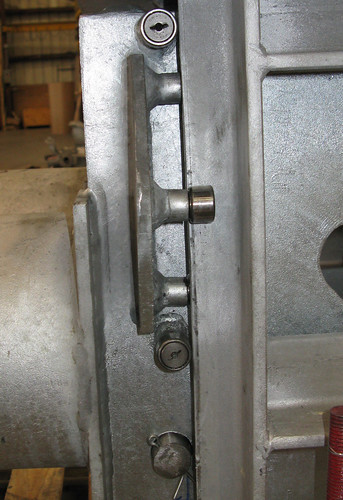
U-Type Constants with Rollers to Reduce Friction

July 29, 2009
U-Type Constants with Rollers to Reduce Friction
Rollers

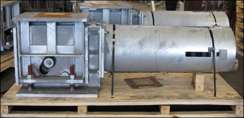
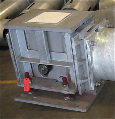
This constant utilizes sealed cam follower roller bearings in place of slide plates that are generally used between the moving table and stationary frame. The rollers help to reduce the friction on the table, reduce residual loads which improve constant deviation, and help to restrict table movement in horizontal directions. These U-Type constants are fabricated from A36 carbon steel with dimensions of 28″H x 37″L x 17″W. The boxing, bolting patterns and loading table location are custom designed per customer specifications. The design also includes a graphite plate bonded to the top of the load flange to reduce the friction between the constant load flange and the saddle support above it. The supports are designed to carry 3015 lb. of piping load with an upward travel of 6″. The constants underwent standard load and travel testing before being shipped to an energy plant.

Want to learn more about constant springs? Instantly view an archived constant webinar!
access-our-webinar-archives

Read More

Flue Gas Duct Damper

July 15, 2009


Flue Gas Duct Damper

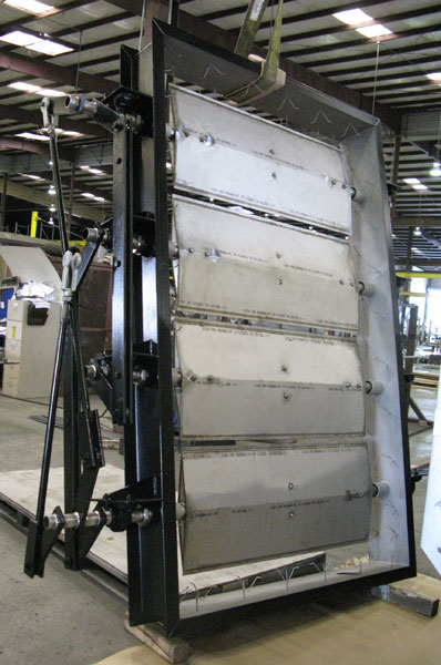
This damper was fabricated from a combination of 304 stainless steel and Inconel®. It is designed as a shut-off damper to control the flow of flue gas in an ammonia plant. The damper will be connected to a motor-driven control system by the linkage shown in the picture. The overall dimensions are 10′ x 6′ with a weight of 2,200 lb. It was painted with standard inorganic zinc primer and top coat per customer specifications. The damper went through visual inspection, dye-penetrant, and functional testing before being shipped to the customer. Refractory lining, utilized to withstand the high temperatures, will be added during installation.

Do you have an application that requires a damper? Get pricing today!
request-a-quote

Read More

Pre-Insulated Base Supports for a LNG Plant

July 1, 2009
Pre-Insulated Base Supports for a LNG Plant
Front View

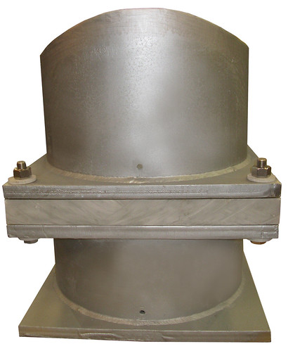
These low-temperature base supports are fabricated from carbon steel with a hot dipped galvanize finish and range from 23″ to 37″ in height. The supports are 18″ in diameter with a base plate of 20″W x 20″L x 1″H and are designed to support pipes ranging in size from 24″ to 30″. The base supports are fabricated with micarta insulation and will be utilized in a LNG plant as a base beneath a cold temperature pipe.

Do you require pre-insulated supports for your project? Get a quote today!
request-a-quote


Read More

48″ Guided Pre-Insulated Pipe Supports for High Temperatures

June 24, 2009
48" Guided Pre-Insulated Pipe Supports for High Temperatures

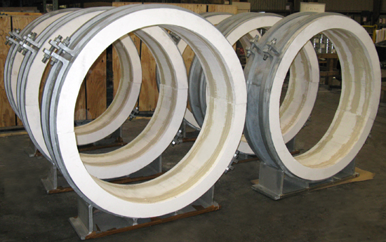
Pipe Shields, Inc., a subsidiary of Piping Technology & Products, Inc., designed these pre-insulated supports for a pipe size of 48″. The clamp and base are fabricated from carbon steel that includes a hot dipped galvanized finish. The 4″ thick insulation is a high density calcium silicate. These guided supports allow for a maximum axial travel of plus or minus 4 1/2″ and have a vertical load rating of 7,100 lb. The operating temperature of the pipe may exceed 1,200ºF, therefore the hot shoes are designed for 1,700ºF. These heavy duty base mounted pipe supports are specially designed to be installed on four emergency diesel exhaust mufflers in a hospital.

Do you need hot shoes for your current or future project? Get pricing today!
request-a-quote

Read More

48″ I.D. ASME Code Process Vessel

June 10, 2009


48" I.D. ASME Code Process Vessel

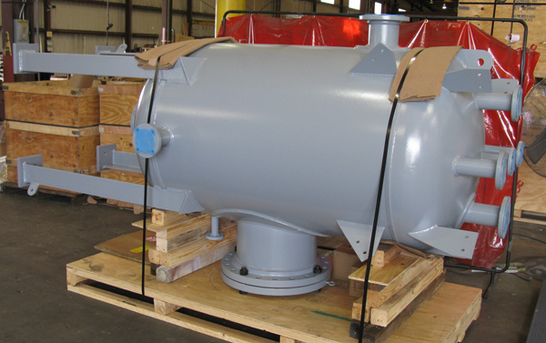
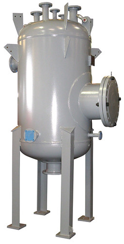
This process vessel has an inside diameter of 48″ and measures 60″ tangent to tangent. The overall height of this vessel is 81″, and measures 120″ including the legs. It is fabricated from 1/2″ 516-70 carbon steel material. This vessel is designed and fabricated according to ASME Section VIII Div 1 codes. It has a capacity of 500 gallons with an internal design pressure of 50 PSIG. The maximum acceptable working pressure is 178 PSIG. This process vessel was heat treated for stress corrosion resistance in the field and 100% x-ray tested and hydro-tested at 231 PSIG prior to being shipped to the customer. This vessel was designed for the customer as a replacement vessel for one in the field that had already provided 20 years of service in a mildly corrosive environment.

Sweco Fab, Inc. worked with the customer to provide a vessel that was even more efficient than the previous one by including 1/8″ thicker walls, an additional 12″ between tangents, heat treatment, an internal drip plate, and an OSHA compliant ladder and platform.

Want to learn more about pressure vessels and tanks? Watch a Sweco Fab webinar now!

access-our-webinar-archives

Read More

Sway Strut Assemblies with Custom Designed 3-Bolt Pipe Clamps

May 13, 2009


Sway Strut Assemblies with Custom Designed 3-Bolt Pipe Clamps
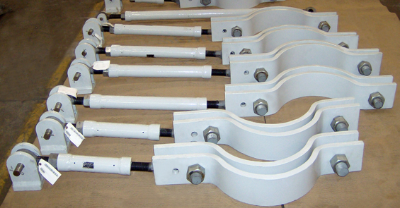
These sway strut assemblies are designed in conjunction with custom three-bolt clamps to prevent movement on the pipeline. The sway struts range in length from 25″ to 70″ from pin to pin. The operating load ranges between 8,000 lb. to 15,000 lb. The clamps are designed for pipe sizes ranging from 8″ to 24″. The sway strut assemblies are fabricated entirely from carbon steel with a hot-dipped galvanize finish. The completed assemblies also include a custom 2-coat paint system that was applied over the galvanize finish before being shipped to an LNG plant overseas.

Do you see a need for sway struts in your piping system? Get pricing today!
request-a-quote

Read More

126″ Long Sway Braces for a Power Plant

April 22, 2009
126" Long Sway Braces for a Power Plant
Sway Braces

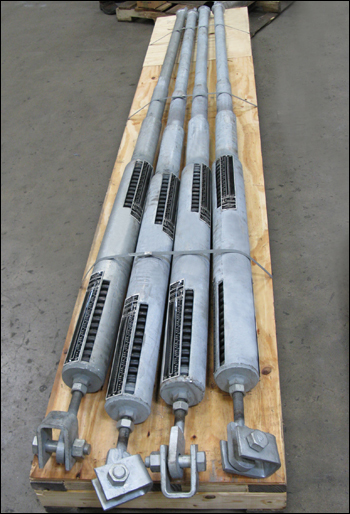
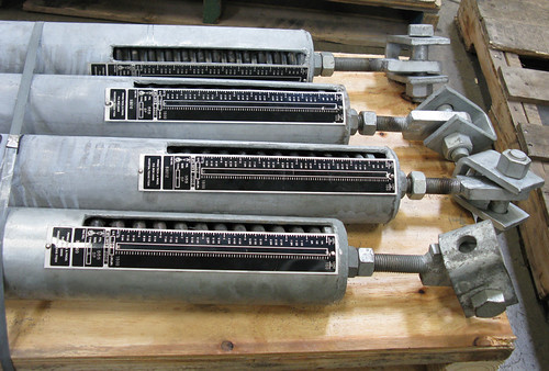
These PT&P sway braces are fabricated from carbon steel and measure 126″ from pin to pin. They use an integral piston assembly with guide to eliminate any buckling and/or misalignment during extension and compression. The sway braces are designed for 10 1/2″ of travel and a load of 1,500 lb. A combination of standard spring coils is used to achieve the required spring rate of 150 lb./in.

Prior to shipment, a test was performed using a hydraulic ram. This test simulated actual field conditions and allowed the sway brace to move through the entire travel range in both compression and extension modes.

Want to learn more about sway braces? Watch a shock & vibration control webinar now!
access-our-webinar-archives

Read More

C-Type Constant with Special Lugs for a Power Plant

April 8, 2009


C-Type Constant with Special Lugs

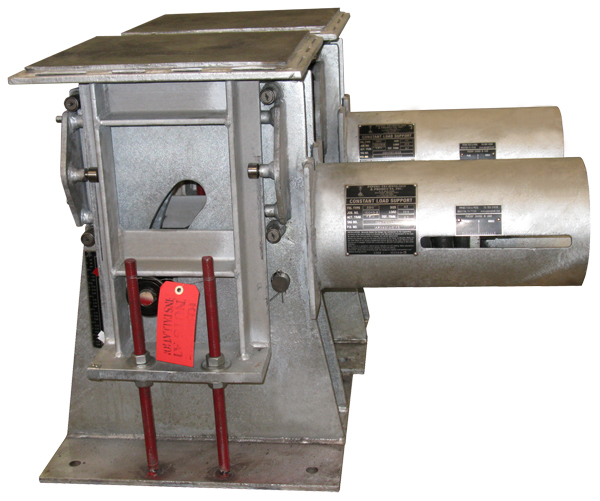
This PT&P 100 C-Type constant spring support was designed in conjunction with special lugs to fit inside of a trolley. The lugs will provide for movement up and down, as well as extensive horizontal movement. This constant was fabricated entirely from A-36 carbon steel with a hot-dipped galvanize finish. The constant measures 16″ wide x 25″ long x 56″ high. It is designed to carry 16,164 lb. of piping load with a travel of 3 1/2″ downward. The lugs will fit within a trolley by a single pin connection. This configuration will prevent swinging by maintaining the constant in an upright position, which will ensure proper functionality and eliminate any load deviation.

Do you require constants for an upcoming project? Get pricing today!
request-a-quote

Read More

200 U-Type Constant Spring Supports with Slide Plates to Reduce Friction

March 25, 2009
200 U-Type Constant Spring Supports with Slide Plates
200 U-Type Constant Spring Supports with Slide Plates to Reduce Friction
200 U-Type Constant Spring Supports with Slide Plates
Slide Plate on Constant

These custom designed constants will be utilized for a heavy load of 109,000 lb. They are designed for a downward travel of 1 1/2″. In order to support the heavy load and low take-off, the constants are designed with an inner and outer spring coil with the outer coil measuring 56″L with a 18 3/4″ O.D. These U-Type constants are fabricated from A36 carbon steel with a hot-dipped galvanize finish.

The dimensions of the constant are 31″H x 90″L x 32″W. The image above shows a PTFE, 25% glass filled slide plate on top to reduce the friction between the constant load flange and the structure above the support. The constant also includes slide plates between the table and the frame of the constant to reduce the friction on the table and improve constant deviation.

Do you require similar spring supports for your job? Get pricing today!

request-a-quote

Read More

120 3/8″ Long Custom Variable Spring Supports with Four Individual Coils

March 11, 2009

120 3/8" Long Custom Variable Spring Supports with Four Individual Coils

These variable springs are custom designed from carbon steel material. The springs are fabricated with extra long housings to allow for a pre-compression lower than the standard. This ensured that the starting (cold) load of 26,745 lb. could be achieved. The springs are designed for a movement of 5.55″ downward, which would produce an operating load for each assembly of 38,305 lb. These springs are to be utilized in pairs together with a 22″ riser clamp to produce a 407″ total pipe hanger assembly length and an overall combined operating load of 76,610 lb.

Want to learn more about variable springs? Watch a past variable springs webinar today!
access-our-webinar-archives

Read More
Top