Beam Attachments
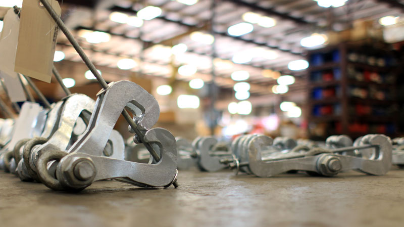
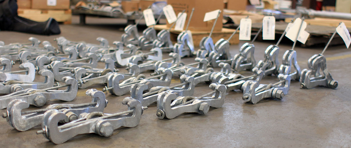
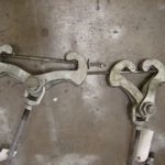
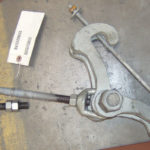
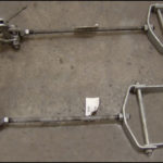
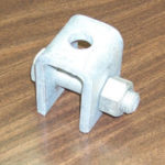
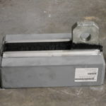
A beam attachment is a type of forged or fabricated clamp that is used to attach rod hangers to beams by clamping onto the load flange. It is used for the suspension of light loads from standard I-beams and wide flange beams.
Ammonia Plant
Chemical Plant
Clean Fuels
Commercial
Electric Plant
Energy Facility
Ethylene Plant
LLDPE Chemical Plant
LNG Plant
MTBE Plant
Natural Gas Combined Cycle Facility
Natural Gas Processing & Separation
Oil Refinery
Oil Sand Mine
Paper Manufacturer
See All
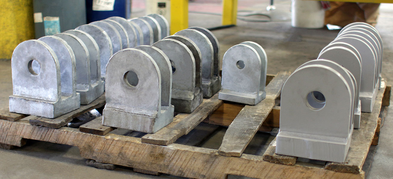
A welding lug is a pipe support component consisting of a single plate of varying thickness, depending upon the load, ...Continue Reading
Our concrete clevis plate is a method for attaching a welded beam attachment to a concrete base in place of ...Continue Reading
You can use a variety of components. The most common would be astructural welding lug or a welded beam attachment. ...Continue Reading
More FAQs…
GENERAL DIMENSIONS & SPECIFICATIONS
- Fig. 20: Welded Beam Attachment
- Fig. 72 & 72L: Welding Lug
- Fig. 73: Concrete Clevis Plate
- Fig. 74: Concrete Single Lug Plate
- Fig. 75: Channel Assembly
- Fig. 76: Welding Lug for Long Radius Elbow
- Fig. 135: Malleable Beam Clamp
- Fig. 140: Heavy Duty Beam Clamp
- Fig. 270: Horizontal Travelers
Fig. 20: Welded Beam Attachment
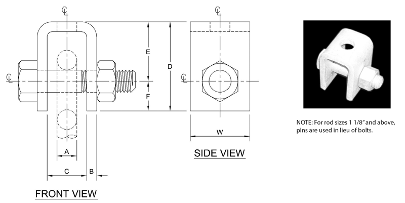
MATERIAL: Carbon steel
ORDERING: Specify figure number, rod size, description and finish. Steel attachment for welding to bottom flange or structural members which will accommodate eye rods or lug attachments. This unit permits rod swing, thereby making it suitable for pipes with horizontal movement.
| SIZE NO. | ROD SIZE A | MAX. LOAD, lbs. | B | C | D | E | F | W | BOLT/PIN SIZE |
WEIGHT (lb./ 100) |
|---|---|---|---|---|---|---|---|---|---|---|
| 3 | 3/8 | 730 | 1/4 | 1 1/4 | 2 7/8 | 2 | 7/8 | 2 | 1/2 x 2 1/2 | 121 |
| 4 | 1/2 | 1350 | 1/4 | 1 1/4 | 2 7/8 | 2 | 7/8 | 2 | 5/8 x 2 1/2 | 130 |
| 5 | 5/8 | 2160 | 1/4 | 1 1/4 | 2 7/8 | 2 | 7/8 | 2 | 3/4 x 3 | 160 |
| 6 | 3/4 | 3230 | 3/8 | 1 1/2 | 3 1/8 | 2 | 1 1/8 | 2 1/2 | 7/8 x 3 1/2 | 280 |
| 7 | 7/8 | 4480 | 3/8 | 2 | 4 1/4 | 3 | 1 1/4 | 2 1/2 | 1 x 4 | 390 |
| 8 | 1 | 5900 | 1/2 | 2 | 4 1/2 | 3 | 1 1/2 | 3 | 1 1/8 x 4 1/2 | 630 |
| 9 | 1 1/8 | 6200 | 1/2 | 2 1/4 | 4 3/4 | 3 | 1 3/4 | 3 | 1 1/4 x 4 1/2 | 630 |
| 10 | 1 1/4 | 9500 | 5/8 | 2 1/2 | 5 | 3 | 2 | 4 | 1 3/8 x 5 | 1021 |
| 12 | 1 1/2 | 13800 | 3/4 | 3 | 6 1/2 | 4 | 2 1/2 | 5 | 1 5/8 x 5 3/4 | 1900 |
| 14 | 1 3/4 | 18600 | 3/4 | 3 3/4 | 7 3/4 | 5 | 2 3/4 | 5 | 1 7/8 x 6 7/8 | 2425 |
| 16 | 2 | 24600 | 3/4 | 3 3/4 | 8 1/4 | 5 | 3 1/4 | 6 | 2 1/4 x 6 7/8 | 3060 |
| 18 | 2 1/4 | 32300 | 3/4 | 4 1/4 | 9 1/2 | 6 | 3 1/2 | 6 | 2 1/2 x 7 3/8 | 3688 |
| 20 | 2 1/2 | 39800 | 3/4 | 4 1/2 | 9 3/4 | 6 | 3 3/4 | 6 | 2 3/4 x 7 5/8 | 3924 |
| 22 | 2 3/4 | 49400 | 5/8 | 3 3/4 | 9 3/4 | 5 3/4 | 4 | 6 | 3 x 7 | 4080 |
| 24 | 3 | 60100 | 5/8 | 3 3/4 | 10 1/4 | 6 1/4 | 4 | 7 | 3 1/4 x 7 | 4670 |
Fig. 72 & 72L: Welding Lug

MATERIAL: Carbon steel
SERVICE: Fig. 72 is used for attaching variable springs and forged clevises to structural members.
ORDERING: Specify figure number, rod size, description and finish.
| ROD SIZE | Fig. 72 Standard A | Fig. 72L Long A1 | B | C | H | T | MAX. LOAD (lb.) |
|---|---|---|---|---|---|---|---|
| 1/2 | 1 1/2 | 3 | 1 1/4 | 2 1/2 | 11/16 | 1/4 | 1350 |
| 5/8 | 1 1/2 | 3 | 1 1/4 | 2 1/2 | 13/16 | 1/4 | 2160 |
| 3/4 | 1 1/2 | 3 | 1 1/4 | 2 1/2 | 15/16 | 3/8 | 3230 |
| 7/8 | 2 | 3 | 1 1/4 | 2 1/2 | 1 1/8 | 3/8 | 4480 |
| 1 | 2 | 3 | 1 1/2 | 3 | 1 1/4 | 1/2 | 5900 |
| 1 1/8 | 3 | 4 | 1 1/2 | 3 | 1 3/8 | 1/2 | 6230 |
| 1 1/4 | 3 | 4 | 2 | 4 | 1 1/2 | 5/8 | 9500 |
| 1 1/2 | 3 | 4 1/2 | 2 1/2 | 5 | 1 3/4 | 3/4 | 13800 |
| 1 3/4 | 3 | 4 1/2 | 2 1/2 | 5 | 2 | 3/4 | 18600 |
| 2 | 4 | 4 1/2 | 3 | 6 | 2 3/8 | 3/4 | 24600 |
| 2 1/4 | 4 1/2 | 5 | 3 | 6 | 2 5/8 | 3/4 | 32300 |
| 2 1/2 | 4 1/2 | 5 | 4 | 8 | 2 7/8 | 1 | 39800 |
| 2 3/4 | 4 1/2 | 5 | 4 | 8 | 3 1/8 | 1 | 49400 |
| 3 | 5 | 5 1/2 | 4 | 8 | 3 3/8 | 1 | 60100 |
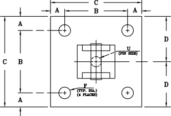
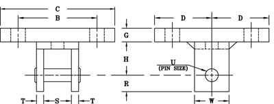
Fig. 73: Concrete Clevis Plate
MATERIAL: Carbon steel
SIZE: Rod sizes 3/8” thru 2”
FINISH: Black or galvanized; furnished black unless otherwise specified.
SERVICE: Attachment for concrete ceiling.
ORDERING: Specify figure number, rod size, description and finish.
| ROD SIZE | MAX. LOAD, lb. | A | B | C | D | F | G | H | R | S | T | U | W | APPROX. WEIGHT lb. |
|---|---|---|---|---|---|---|---|---|---|---|---|---|---|---|
| 3/8 | 730 | 1 | 8 | 10 | 5 | 9/16 | 3/8 | 2 | 7/8 | 1 1/4 | 1/4 | 1/2 | 2 | 11.8 |
| 1/2 | 1350 | 1 | 8 | 10 | 5 | 9/16 | 3/8 | 2 | 7/8 | 1 1/4 | 1/4 | 5/8 | 2 | 11.9 |
| 5/8 | 2160 | 1 | 8 | 10 | 5 | 9/16 | 1/2 | 2 | 1 | 1 1/4 | 1/4 | 3/4 | 2 | 15.7 |
| 3/4 | 3230 | 1 | 8 | 10 | 5 | 11/16 | 1/2 | 2 | 1 1/8 | 1 1/2 | 3/8 | 7/8 | 2 1/2 | 16.9 |
| 7/8 | 4480 | 1 | 8 | 10 | 5 | 11/16 | 1/2 | 3 | 1 1/4 | 2 | 3/8 | 1 | 2 1/2 | 18.1 |
| 1 | 5900 | 2 | 8 | 12 | 6 | 13/16 | 3/4 | 3 | 1 1/2 | 2 | 1/2 | 1 1/8 | 3 | 36.9 |
| 1 1/4 | 9500 | 2 | 8 | 12 | 6 | 15/16 | 3/4 | 3 | 2 | 2 1/2 | 5/8 | 1 3/8 | 4 | 40.9 |
| 1 1/2 | 13800 | 2 | 8 | 12 | 6 | 1 1/8 | 1 | 4 | 2 1/2 | 3 | 3/4 | 1 5/8 | 5 | 59.8 |
| 1 3/4 | 18600 | 2 | 10 | 14 | 7 | 1 3/8 | 1 1/4 | 5 | 2 3/4 | 3 3/4 | 3/4 | 1 7/8 | 5 | 93.6 |
| 2 | 20700 | 2 | 10 | 14 | 7 | 1 3/8 | 1 1/4 | 5 | 3 1/4 | 3 3/4 | 3/4 | 2 1/4 | 6 | 100.0 |
Fig. 74: Concrete Single Lug Plate
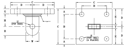
MATERIAL: Carbon steel
SIZE: Rod sizes ½” thru 2”
FINISH: Black or galvanized; furnished black unless otherwise specified.
SERVICE: Structural attachment for concrete ceiling. Lug is used in conjunction with Fig. 95 (Forged Steel Clevis).
ORDERING: Specify figure number, rod size, description and finish.
| ROD SIZE | MAX.RECOM. LOAD, lb. | A | B | C | D | E | F | G | H | R | T | U | W | APPROX. WEIGHT lb. |
|---|---|---|---|---|---|---|---|---|---|---|---|---|---|---|
| 1/2 | 1350 | 1 | 8 | 10 | 5 | 4 7/8 | 9/16 | 3/8 | 1 1/2 | 1 1/4 | 1/4 | 5/8 | 2 1/2 | 11.1 |
| 5/8 | 2160 | 1 | 8 | 10 | 5 | 4 7/8 | 9/16 | 1/2 | 1 1/2 | 1 1/4 | 1/4 | 3/4 | 2 1/2 | 14.6 |
| 3/4 | 3230 | 1 | 8 | 10 | 5 | 4 13/16 | 11/16 | 1/2 | 1 1/2 | 1 1/4 | 3/8 | 7/8 | 2 1/2 | 14.8 |
| 7/8 | 4480 | 1 | 8 | 10 | 5 | 4 13/16 | 11/16 | 3/4 | 2 | 1 1/4 | 3/8 | 1 | 2 1/2 | 22.0 |
| 1 | 5900 | 2 | 8 | 12 | 6 | 5 3/4 | 13/16 | 3/4 | 2 | 1 1/2 | 1/2 | 1 1/8 | 3 | 31.9 |
| 1 1/4 | 9500 | 2 | 8 | 12 | 6 | 5 11/16 | 15/16 | 1 | 3 | 2 | 5/8 | 1 3/8 | 4 | 43.8 |
| 1 1/2 | 13800 | 2 | 8 | 12 | 6 | 5 5/8 | 1 1/8 | 1 | 3 | 2 1/2 | 3/4 | 1 5/8 | 5 | 45.6 |
| 1 3/4 | 18600 | 2 | 8 | 12 | 6 | 5 5/8 | 1 3/8 | 1 1/4 | 3 | 2 1/2 | 3/4 | 1 7/8 | 5 | 55.7 |
| 2 | 24600 | 2 | 8 | 12 | 6 | 5 5/8 | 1 3/8 | 1 1/4 | 4 | 3 | 3/4 | 2 1/4 | 6 | 58.2 |
Fig. 75: Channel Assembly
ORDERING: Specify figure number, rod size, channel size, C-to-C and “E” dimension and material required.
E = C-to-C + 2L + W
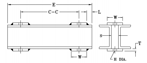
| ROD SIZE | 3/8 | 1/2 | 5/8 | 3/4 | 7/8 | 1 | 1 1/8 | 1 1/4 | 1 1/2 | 1 3/4 | 2 | 2 1/4 | 2 1/2 | 2 3/4 | 3 | 3 1/4 | 3 1/2 |
|---|---|---|---|---|---|---|---|---|---|---|---|---|---|---|---|---|---|
| H HOLE | 1/2 | 5/8 | 3/4 | 7/8 | 1 | 1 1/4 | 1 3/8 | 1 1/2 | 1 3/4 | 2 | 2 1/4 | 2 1/2 | 2 3/4 | 3 | 3 1/4 | 3 1/2 | 3 3/4 |
| S | 9/16 | 11/16 | 13/16 | 15/16 | 1 1/16 | 1 3/8 | 1 1/2 | 1 5/8 | 1 7/8 | 2 1/4 | 2 1/2 | 2 3/4 | 3 | 3 1/4 | 3 1/2 | 3 3/4 | 4 |
| W | 3 | 3 | 3 | 4 | 4 | 4 | 4 | 5 | 5 | 5 | 5 | 6 | 6 | 6 | 6 | 6 | 7 |
| T | 1/4 | 1/4 | 3/8 | 3/8 | 1/2 | 1/2 | 1/2 | 1/2 | 3/4 | 3/4 | 3/4 | 3/4 | 3/4 | 3/4 | 3/4 | 3/4 | 3/4 |
| L | 1/4 | 1/4 | 1/4 | 1/4 | 1/4 | 1/4 | 1/4 | 1/4 | 1/4 | 1/4 | 1/4 | 1/4 | 1/4 | 1/4 | 3/8 | 3/8 | 3/8 |
Safe Load Table
| C-to-C = SPAN IN INCHES | ||||||||||||||||
|---|---|---|---|---|---|---|---|---|---|---|---|---|---|---|---|---|
| NOMINALSIZE | WEIGHT per ft. 2 C’s | 12 | 14 | 16 | 18 | 20 | 22 | 24 | 26 | 28 | 30 | 36 | 42 | 48 | 54 | 60 |
| MAXIMUM SAFE LOAD IN KIPS | ||||||||||||||||
| 3 | 8.2 | 8.8 | 7.5 | 6.6 | 5.8 | 5.2 | 4.8 | 4.4 | 3.9 | 3.6 | 3.5 | 2.9 | 2.5 | 2.2 | 1.9 | 1.7 |
| 4 | 10.8 | 15.2 | 13.1 | 11.4 | 10.2 | 9.1 | 8.3 | 7.5 | 7.0 | 6.5 | 6.1 | 5.1 | 4.3 | 3.8 | 3.3 | 3.0 |
| 5 | 13.4 | 24.0 | 20.6 | 18.0 | 16.0 | 14.4 | 13.1 | 12.0 | 11.1 | 10.3 | 9.6 | 8.0 | 6.8 | 6.0 | 5.3 | 4.8 |
| 6 | 21.0 | 40.0 | 34.3 | 30.0 | 26.6 | 24.0 | 21.8 | 20.0 | 18.4 | 17.1 | 16.0 | 13.3 | 11.4 | 10.0 | 8.8 | 8.0 |
| 8 | 23.0 | 64.8 | 55.5 | 48.6 | 43.2 | 38.8 | 35.3 | 32.3 | 29.8 | 27.7 | 25.8 | 21.5 | 18.5 | 16.1 | 14.3 | 12.9 |
| 10 | 30.6 | 107.2 | 91.7 | 80.3 | 71.4 | 64.2 | 58.4 | 53.5 | 49.4 | 45.8 | 42.8 | 35.7 | 30.6 | 26.7 | 23.8 | 21.4 |
| 12 | 41.4 | 171 | 147 | 128 | 114 | 103 | 93.4 | 85.6 | 79.0 | 73.3 | 68.4 | 57.0 | 48.9 | 42.8 | 38.0 | 34.2 |
| 15 | 67.8 | 333 | 286 | 250 | 222 | 200 | 182 | 167 | 154 | 143 | 133 | 111 | 95.3 | 83.4 | 74.1 | 66.7 |
Fig. 76: Welding Lug for Long Radius Elbow
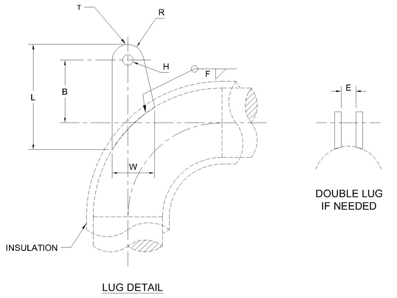
SIZE RANGE: 3” thru 42”
MATERIAL: Carbon steel
FINISH: Black or galvanized; furnished black unless otherwise specified.
SERVICE: Attachment for concrete ceiling.
ORDERING: Specify figure number, pipe size, description and finish, operating temperature and any other special requirements.
NOTES: The lugs are designed for 4” insulation thickness. Lugs can be designed for different insulation thickness.
| ROD SIZE | 1/2″ | 5/8″ | 3/4″ | 7/8″ | 1″ | 1-1/8″ | 1-1/4″ | 1-1/2″ | 1-3/4″ | 2″ | 2-1/4″ | 2-1/2″ | 2-3/4″ | 3″ | |
| T | 1/4 | 1/4 | 3/8 | 1/2 | 1/2 | 5/8 | 3/4 | 3/4 | 3/4 | 3/4 | 3/4 | 1 | 1 | 1 | |
| W | 3 1/2 | 3 1/2 | 3 1/2 | 3 1/2 | 5 | 5 | 6 | 7 | 7 | 8 1/2 | 8 1/2 | 9 3/4 | 10 1/4 | 10 1/2 | |
| R | 1 1/2 | 1 1/2 | 1 1/2 | 1 1/2 | 2 | 2 | 2 1/2 | 3 | 3 | 3 1/2 | 3 1/2 | 3 3/4 | 4 | 4 | |
| H | 11/16 | 13/16 | 15/16 | 1 1/8 | 1 1/4 | 1 3/8 | 2 | 1 3/4 | 2 | 2 3/8 | 2 5/8 | 2 7/8 | 3 1/8 | 3 3/8 | |
| E | 1 | 1 | 1 | 1 1/2 | 1 1/2 | 2 | 2 | 2 | 2 1/2 | 2 1/2 | 2 1/2 | 2 1/2 | 2 1/2 | 2 1/2 | |
| F | 1/8 | 1/8 | 1/4 | 1/4 | 1/4 | 5/16 | 5/16 | 5/16 | 5/16 | 3/8 | 3/8 | 3/8 | 3/8 | 3/8 | |
| PIPE SIZE | B. DIM | L. DIM | |||||||||||||
| 3 | 7 7/16 | 11 11/16 | 11 11/16 | 11 11/16 | 11 11/16 | ||||||||||
| 4 | 7 1/2 | 11 9/16 | 11 9/16 | 11 9/16 | 11 9/16 | 13 1/2 | 13 1/2 | ||||||||
| 6 | 7 9/16 | 11 5/8 | 11 5/8 | 11 5/8 | 11 5/8 | 13 1/16 | 13 1/16 | 14 11/16 | 16 13/16 | 16 13/16 | |||||
| 8 | 7 7/16 | 11 13/16 | 11 13/16 | 11 13/16 | 11 13/16 | 13 1/16 | 13 1/16 | 14 1/2 | 16 1/16 | 16 1/16 | 17 7/8 | 17 7/8 | 18 15/16 | 20 1/4 | 20 1/4 |
| 10 | 7 5/16 | 11 7/8 | 11 7/8 | 11 7/8 | 11 7/8 | 13 1/16 | 13 1/16 | 14 3/8 | 15 3/4 | 15 3/4 | 17 5/16 | 17 5/16 | 18 1/8 | 18 15/16 | 18 15/16 |
| 12 | 7 1/8 | 12 | 12 | 12 | 13 3/16 | 13 3/16 | 14 7/16 | 15 3/4 | 15 3/4 | 17 1/8 | 17 1/8 | 17 7/8 | 15 5/8 | 15 5/8 | |
| 14 | 6 3/8 | 12 1/4 | 12 1/4 | 13 7/16 | 13 7/16 | 14 11/16 | 15 15/16 | 15 15/16 | 17 5/16 | 17 5/16 | 18 1/8 | 18 3/4 | 18 3/4 | ||
| 16 | 6 1/8 | 12 15/16 | 13 1/2 | 13 1/2 | 14 11/16 | 15 15/16 | 15 15/16 | 17 1/4 | 17 1/4 | 17 15/16 | 18 5/8 | 18 5/8 | |||
| 18 | 5 13/16 | 13 1/2 | 13 1/2 | 14 11/16 | 15 15/16 | 15 15/16 | 17 3/16 | 17 3/16 | 17 7/8 | 18 1/2 | 18 1/2 | ||||
| 20 | 6 3/4 | 14 3/4 | 15 7/8 | 17 | 17 | 18 3/8 | 18 3/8 | 19 | 19 11/16 | 19 11/16 | |||||
| 24 | 7 1/4 | 17 1/4 | 18 3/8 | 18 3/8 | 19 1/2 | 19 1/2 | 20 1/8 | 20 11/16 | 20 11/16 | ||||||
| 30 | 7 | 20 | 20 | 20 5/8 | 21 5/8 | 21 5/8 | |||||||||
| 36 | 7 | 21 1/8 | 21 1/8 | 21 3/4 | 22 5/16 | 22 5/16 | |||||||||
| 42 | 6 | 21 1/4 | 21 1/4 | 21 7/8 | 22 5/16 | 22 5/16 |
Fig. 135: Malleable Beam Clamp

MATERIAL: Malleable iron
FINISH: Black
SERVICE: Recommended for attachment to structural steel. Use in conjunction with American Standard I-Beams and wide flange beams where beam widths are from a min. of 2 3/8” to a max. of 7” and flange thickness does not exceed 0.60”.
ORDERING: Specify figure number and description.
| MAXIMUM ROD SIZE | BOLT DIA | ROD TAKE OUT (E)-FOR WITH OF BEAM FLANGE | MAX. RECOM. LOAD (lb.) | APPROX. WEIGHT (lb. per each) | |||||
| 2 3/8 | 3 | 4 | 5 | 6 | 7 | ||||
| 7/8 | 7/16 | 3 1/2 | 3 7/16 | 3 5/16 | 2 15/16 | 2 9/16 | 1 7/8 | 1365 | 2.2 |
Fig. 140: Heavy Duty Beam Clamp
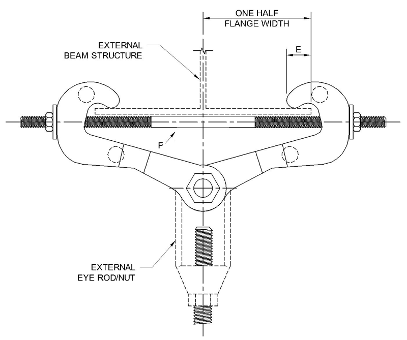
MATERIAL: Carbon steel
FINISH: Painted, shop primed or galvanized.
SERVICE: For suspension of heavy loads from standard I-Beams and wide flange beams with flange widths to 15” and flange thickness to 1.07”.
ORDERING: Specify figure number, rod size, description, clamp size, beam size and finish.
| CLAMP SIZE | E | F | MAX. LOAD lbs. | APPROX. WEIGHT / each | MAXIMUM FLANGE | |
|---|---|---|---|---|---|---|
| THK. | WIDTH | |||||
| 1 | 1 | .375 | 11500 | 9 | 1.07 | 10 |
| 2 | 1 | .375 | 11500 | 11 | 1.07 | 15 |
Fig. 270: Horizontal Travelers
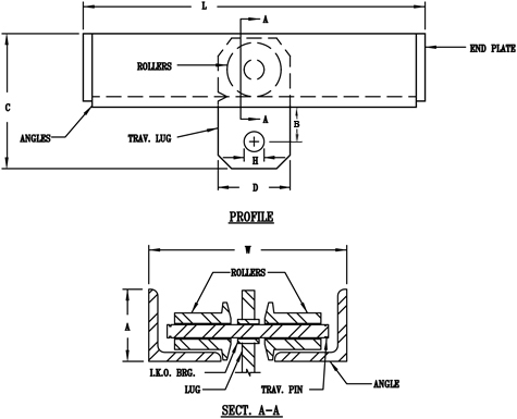
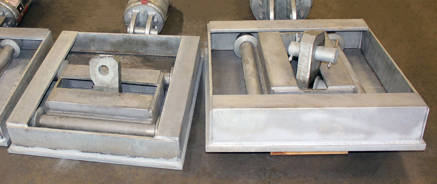
SIZE RANGE: Available in four sizes to take loads up to 20,700 lb. All sizes provide for 12” of horizontal travel.
INSTALLATION: Shipped ready for installation. Attach to the supporting steel by welding around the frame. Spring hanger may be bolted or welded to the load plate.
ORDERING: Specify figure number, size, description and “H” dimensions if required. Horizontal travelers can be designed for special loads, travels or dual directional travel upon request.
FEATURES:
• Highly economical
• Minimum friction
• Virtually dust proof
• Compact – designed for minimum head room
• Versatile
| SIZE NO. | MAX. LOAD, lb. | APPROX. WEIGHT lb. | A | B | C | D | H MAX. | L | T | W |
|---|---|---|---|---|---|---|---|---|---|---|
| 1 | 3770 | 15 | 2 1/2 | 1 5/8 | 5 3/8 | 2 1/2 | 1 1/8 | 15 1/8 | 3/4 | 4 5/8 |
| 2 | 6230 | 37 | 3 1/2 | 2 5/8 | 7 7/8 | 3 1/2 | 1 3/8 | 16 3/8 | 3/4 | 6 3/4 |
| 3 | 11630 | 69 | 5 | 3 | 10 1/2 | 5 | 1 3/4 | 17 7/8 | 1 | 9 3/4 |
| 4 | 20700 | 102 | 6 | 3 1/2 | 12 1/2 | 6 | 2 1/2 | 19 1/8 | 1 1/2 | 10 1/4 |
hbspt.forms.create({
portalId: “88145”,
formId: “387a2f0a-000b-4fec-ace9-674cd4cf472e”
});

